Leitz Seikkosha TM-20C Theodolite Added to Equipment for Checking Towers for Vertical/Plumb, Pad Layouts, etc.
Primarily for use in my broadcast engineering work, I recently acquired a Leitz-Seikkosha TM-20C Theodolite. Ironically, I found it on eBay and in the process of buying it discovered I was purchasing it from a fellow ham radio operator up in the Atlanta, GA area. He and I turned out to also have serious interest in electronic circuit design and the manufacturing of custom-built electronic circuits and boards, so a great friendship is developing between us.
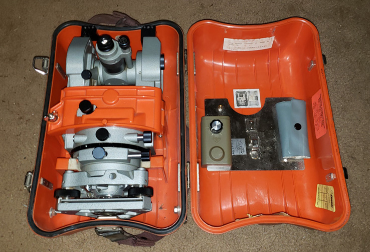
Leitz Seikkosha TM-20C and accessories in its heavy duty storage and carrying case.
I had been searching for an instrument which would give me several capabilities, including (but not limited to):
- Checking towers to make sure they are — and remain — vertically plumb
- Laying out tower pad forms which will be level and square to a high degree of accurace
- Turning accurate angles and properly positioning guy wire anchor points
- Measuring long horizontal distances, along with azimuth and grade information
- Measuring heights of towers and appurtenances (by means of trigonometric calculation based on known distance from tower base, etc.
- Tons of other stuff
This is a very precise, surveyor’s grade instrument

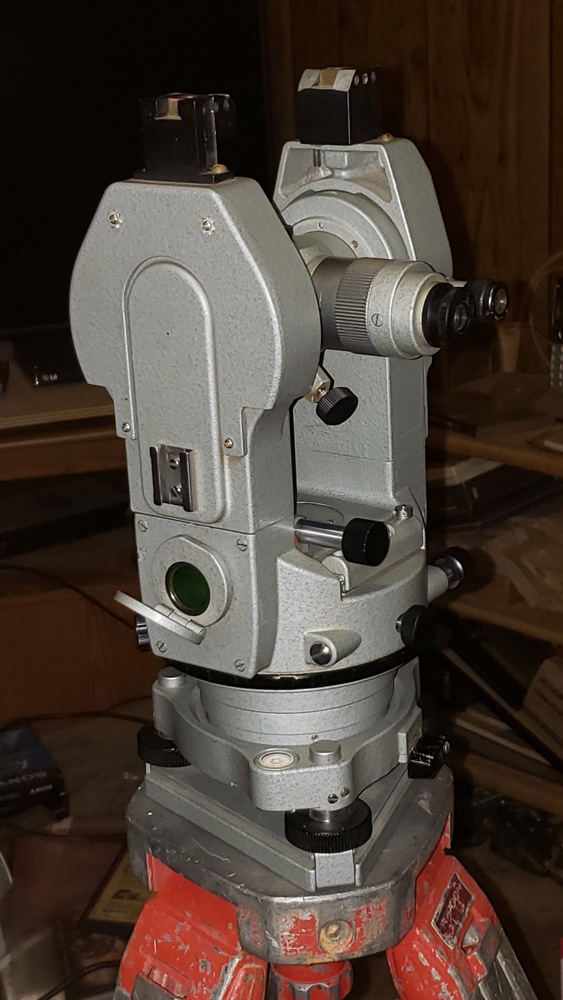
The TM-20C with objective telescope lens shown. A much smaller eyepiece can be seen directly below the telescope objective lens, near the base. The smaller, lower eyepiece is the optical plummet eyepiece, which contains a crosshair reticle for very precisely positioning the Theodolite directly over a known reference point.
View of the TM-20C from the opposite direction, showing the telescope eyepiece and microscope eyepiece.
According to the manufacturer’s specifications, the TM-20C reads horizontal and vertical angles read “… direct to 20 seconds, with estimation to 5 seconds.” For those of us who
prefer to think and speak in degrees and decimal degrees, that equates to a direct read accuracy of 0.00555556 degrees or better, to within 0.00138889 degrees by estimation. If that’s not close enough to being “on the money,” I don’t know what would be.
Viewing the horizontal, vertical, and micrometer scales
Once the instrument is set up and everything is precisely leveled and an azimuth reference is established, the microscope eyepiece is used to read the
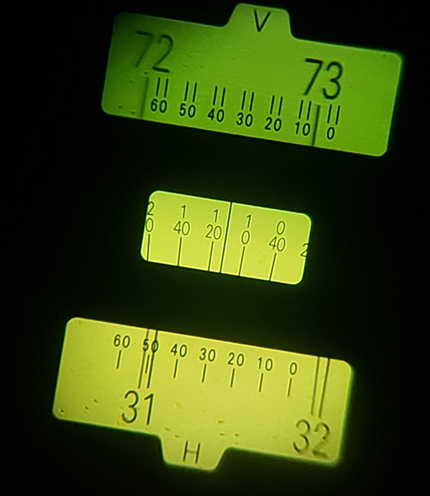
The horizontal and vertical angle scales and the micrometer scale are all shown in a single window, which is viewed through the small microscope eyepiece adjacent to the main telescope.
horizontal and vertical angles. This facilitates either reading the angles between known objects or points, or for establishing the correct position of a new stake, marker, or object based on a known point of reference.
Calibrating the TM-20C for correct horizontal and vertical angles
Because they are mechanical as well as containing very high quality optics, over the course of time and due to being bumped around and handled, these things occasionally get out of calibration. My initial tests showed that the bubble/spirit level used to get the instrument level on its adjustable base (known as a “tribrach”) if it read level (bubble dead-center) and I then rotated the Theodolite 180° the bubble drifted almost fully to one end. This told me that the bubble/spirit level needed calibrating. The way you do this is by inserting a special pin tool in one of the holes on the adjusting screw at the right-hand end of the level and very gingerly turning it so that the bubble moves half the distance back center. Then you rotate it back to the
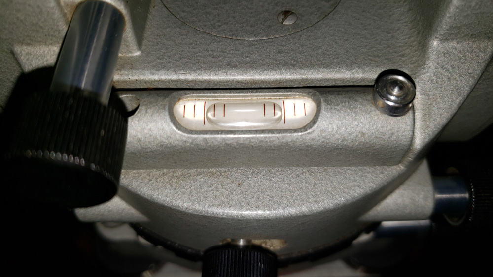
With this bubble/spirit level adjusted correctly and the Theodolite and tribrach correctly leveled, the bubble should stay dead center as seen here, no matter which way the Theodolite is rotated through a full 360° range. The silver adjustment screw can be seen to the right of the level window. There are holes around the circumference of this adjuster for inserting the pin tool and very slightly and carefully turning it in one direction or the other, which moves that end of the level up or down in order to get it to accurately indicate whether or not the Theodolite has been properly leveled when setting it up for use.
first position, adjust the tribrach leveling thumbscrews so that the bubble is dead-center again, rotate the Theodolite 180° again, look at how far off from center the bubble drifts (it should be much less than the first time) and again use the pin to adjust the level so the bubble moves half the distance back to center… and you repeat this process as many times as needed until adjusting the tribrach leveling thumbscrews so that the bubble is dead center and rotating the Theodolite 180° results in the bubble staying dead center. After that, you can truly level the Theodolite and tribrach so that it’s level anywhere in its 360° range of rotation.
Once I had the tribrach bubble/spirit level calibrated, when setting the telescope to the what should be a perfectly level, horizontal view (indicated as 90° vertical angle in the microscope viewfinder), I read the height indication on a grade rod firmly attached to a fence about 66 feet away. I then rotated it 180° on its base and flipped the telescope over 180° (referred to as “plunging” by surveyors) to a vertical angle position indicated at 270° in the microscope. When everything in the optical portions of the instrument are accurately calibrated, doing so should cause the horizontal line in the telescope crosshairs to fall right on the same grade rod height reading. It wasn’t. It was off by just a tad over 1/10 of a foot. This meant that the position of the horizontal line in the telescope crosshairs was out of calibration.
Calibrating the vertical position of the crosshairs for accurate vertical angle measurements
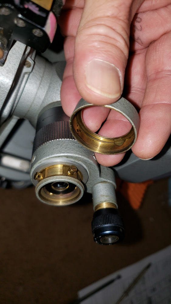
Reticle adjustment cover removed from telescope.
The telecsope crosshairs are adjusted by means of tiny screws which are accessed by screwing the reticle adjustment cover off of the telescope, as can be seen in the photos.
There are four screws for adjusting the reticle to correctly align/position the crosshairs. The upper and lower screws adjust the vertical position, thus adjusting where the horizontal line of the crosshairs appears when looking through the telescope. Similarly, the left and right screws adjust the horizontal position of the reticle, thus adjusting where the vertical crosshair line(s) fall when looking through the telescope. Careful calibration of these is the key to knowing that the vertical and horizontal readings are true and accurate.
To calibrate the vertical angle measurement (horizontal crosshair line) involves taking a height reading on a well secured, very stationary grade rod (the TM-20C manual says the distance to the grade rod should be 75′ to 125′, but a greater distance is cool, yielding even tighter calibration — I used a distance of about 133′) with the telescope adjusted to show a 90° vertical angle, then rotating the Theodolite 180° and “plunging” (flipping) the telescope on its axis and adjusting the fine adjustment know so that it reads 270° vertical (the exact opposite of the first
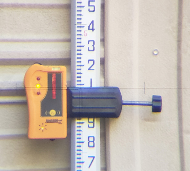
Grade rod used for measuring heights (with a Laser Level target attached in this photo.) If you look closely, you can see the vertical and horizontal crosshair lines, and the “+” center indicator.
position) and noting the height on the grade rod that the horizontal line falls above or below the first reading. With that information, you carefully adjust the upper and lower reticle adjustment screws so that the crosshair crosses the grade rod at a point which falls exactly halfway between the first and second readings. With that done, you rotate the Theodolite and flip the telescope back to the positions where you started (adjusting the telescope so that it’s reading 90° again), take a new height reading, rotate the Theodolite and plunge it again and fine adjust for a 270° reading and if they’re exactly the same, you’re done with the vertical calibration. If they aren’t the same, the difference should be considerably less than the first round, and you simply adjust the screws again to put the reticle line at the midway point between your two measurement readings, then go back to the original position and… rinse… repeat… until they will match precisely.
A similar check (and calibration, if needed) is utilized to make sure vertical crosshair line in the reticle falls where it should for accurate horizontal angle/azimuth measurements. The only difference is that instead of using a vertical height measurement on the grade rod, you set up the Theodolite — nice and level — and with the telescope set for a 90° (horizontally level) view, rotate the upper and lower motion clamp screws as needed so that you see a horizontal reading of 0° (or 360° as shown on some Theodolites) and lock it down. You can draw a vertical line on a wall (or a piece of painter’s tape) on a wall where the crosshair falls, or… well, there are multiple ways to achieve a reference that the vertical crosshair falls on. My trick was to simply strap the grade rod along the side of the fence in a horizontal position, which gave me actual measurement marks so that I had some numbers for calculating the adjustment needed. By first taking a reading or establishing a reference with the Theodolite locked down in the 0° horizontal/azimuth position, then loosening the upper motion clamp and rotating the Theodolite to the 180° horizontal/azimuth position and and plunging/flipping the telescope, you look at where the vertical crosshair line is pointing as compared to the initial reading or mark. Now it’s time to carefully adjust the left and right screws on the reticle adjustment to move the vertical line half the distance toward the original mark or measurement point. Then you spin the Theodolite back around to the 0° horizontal/azimuth position (you’ll discover it doesn’t fall exactly on the original mark or measurement point.) Make a new mark or take a new reading on the horizontally positioned grade rod, rotate and flip the Theodolite and telescope again, check the difference (it should be considerably better than the difference noted in the first round of checking/adjusting), and once again adjust the reticle with the left and right adjusting screws to move the vertical crosshair line half the distance back to the first mark/measurement. It took me three rounds of doing this to nail it down, but once I was done, the vertical line fell dead on the same mark with the Theodolite rotated and plunged back and forth by 180°, so don’t be surprised if it takes several rounds.
Checking to see how well my calibration/adjustment turned out
As mentioned at the start of this post, according to the TM-20C manual, the instrument will “directly” read to 20 seconds and “by estimation” to 5 seconds. As also previously mentioned, these translate to a direct-read accuracy of 0.00555556° and allows for an “estimation” accuracy of 0.00138889°. The word “estimation” is important to keep in mind: that accuracy is not guaranteed. Accuracy tighter than the 20 second level is highly dependent on the operator’s “estimation” of where the fine line in the micrometer falls between 20 second marks. If you’re only working with a couple of measurements, “turn points,” etc., it might not be so bad; however, if you’re doing a complex measurement “circuit” involving multiple points, moving the tripod, Theodolite, and grade rod to more and more locations, the tiny errors in estimations can accumulate. So what does that mean for my purposes?
My goal was to get the Theodolite calibrated well within its stated “direct” read accuracy of 20 seconds (0.00555556°) and as good as could be achieved beyond that for “estimation” purposes. So how did I do?
After completing my calibration work on the thing, I tested by using the surveyor’s method of first measuring and calculating a grade between two points by setting up the instrument at exactly the midpoint of a line between the two points being measured. This mean 66′-6″ along the straight line between my two points (grade rod position) which were 133′ apart. The reason you do a measurement and calculations from the exact midpoint first is this: IF the horizontal line in the reticle/crosshairs is not in the right position, by reading the height on the grade rod at position-A from the midpoint, rotating the Theodolite 180° on its base and reading the height on the grade rod at position-B, any error in the vertical position of the horizontal reticle line will be equal. With the error at both ends identical, you will still get a correct grade measurement and calculation.
The second half of the calibration test involved positioning the instrument to a point much closer to grade rod position-B along the line between the grade rod positions A and B. I was actually set up 16′ from B, and 117′ from grade rod position-A. Then, in a similar fashion to the first half of the test, I read the height indicated by the horizontal reticle line while looking at the grade rod at position-A, then rotated the Theodolite 180° and read the height indicated on the grade rod at position-B. It’s important to note that since the instrument was now not at the midpoint between A and B, if the vertical angle indicated by the Theodolite (supposedly 90° or horizontally level –ideally perfectly level) was not accurate or “true,” it would result in a small error over the short distance to point-B and a considerably larger error over the longer distance to point-A. With the two errors being unequal, the calculated grade distance between points A and B would not be the same as the measurements and calculations from the midpoint setup position. That’s how you truly test the vertical accuracy on a Theodolite. So… just how close and accurate did my calibration turn out?
“Survey says…”
The difference in grade calculation between my midpoint setup measurements and the measurements taken at 117′ from point A and 16′ from point B turned out to be 0.005 feet. Using an online triangle trigonometry function calculator (I’ve long forgotten most of what I learned about trig) I calculated the angle error based on two known values:
-
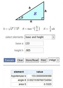
Calculated vertical angle error after calibration of the reticle.
The horizontal distance (the “near side” of an imaginary right triangle, which in this case was 133′, and
- The height of the “opposing” (vertical side of the right triangle), which is the 0.005′ vertical error

The trig calculator came up with the angle at the instrument position being 0.00215398 (rounded, but the image here shows the result to 16 decimal places.) My goal being to be well within the stated “20 second” direct-read accuracy of 0.00555556°, my calculated angle error was only 38.8% of the 20 second “direct” read accuracy for the TM-20C Theodolite.
My result was not quite as good as their “estimation” 5 second accuracy (that’s 0.00138889°) but I maintain that “estimated accuracy” is an oxymoron. Looking at it another way, I didn’t purchase this thing for laying out highways… BUT… if I were in some imaginary universe be called upon to use it for that, based on my tested and calculated vertical error of 0.005′ over 133′ of horizontal distance, my math says that would equate to an error of 0.198′ over the course of a mile — I’d only be off 2-3/8″ inches vertically. Judging by some of the roads we have around here, this thing really would be “good enough for government work,” I suppose.
73 all,
KK4ICE (a/k/a “The Iceman”)
Recent Comments