2m/70cm Dual Band J-Pole
by KK4ICE
If you have any questions about this project, contact KK4ICE@ARRL.NET.
(Step-by-step instructions with photos can be seen below, following the project description and safety disclaimer.)
This is an excellent performing J-Pole type antenna, constructed from readily available materials.
Approximate cost: $35 (not including coax or tools.)
Perhaps the most difficult item to locate for this project is the 3/8″-24 threaded rod. No endorsement is intended here, but the only business in our location that had it was Fastenal.
This project probably deserves a “medium” difficulty rating, primarily because of the tools that make the job easier, such as a drill press and bandsaw. A hacksaw or reciprocating saw with a metal cutting blade, as well as an electric hand drill and vise can be substituted if needed. And please: always wear safety glasses and other appropriate safety equipment for the job and exercise proper caution when using power tools.
 Materials List:
(10′) 1/2″ EMT conduit
(3′) 3/8″-24 threaded rod
(1) 5″ Stanley L-bracket
(3) #12 hose clamps
(3) 3/8″-24 self-locking nuts
(1) antenna mount with internal threads to accept 3/8″-24 antenna element
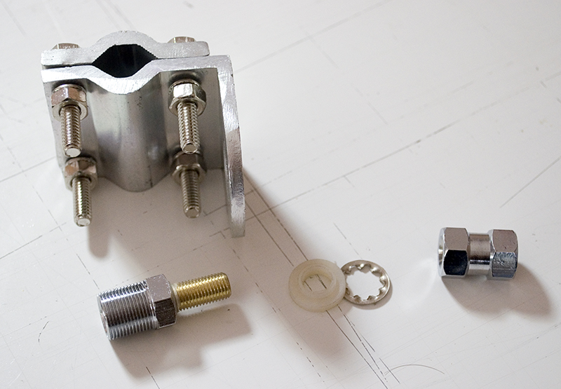 I used a Radio Shack CB antenna mirror/luggage rack mount because it was the only antenna mount available locally. Here you see the actual antenna mount disassembled and removed from the mirror/luggage rack bracket. The white plastic insulator/bushing with this mount requires a 1/2″ hole for mounting on the J-pole assembly.
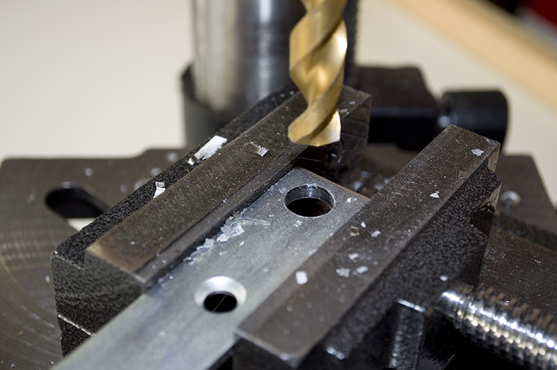 Using the factory drilled holes in the Stanley L-bracket, drill the outer hole out to 1/2″.
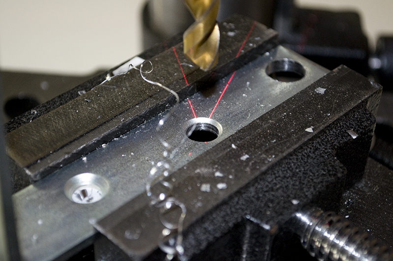 Drill the middle hole on the same part of the bracket out to 3/8″ to accept the short element, which will be cut from the 3/8″ threaded rod.
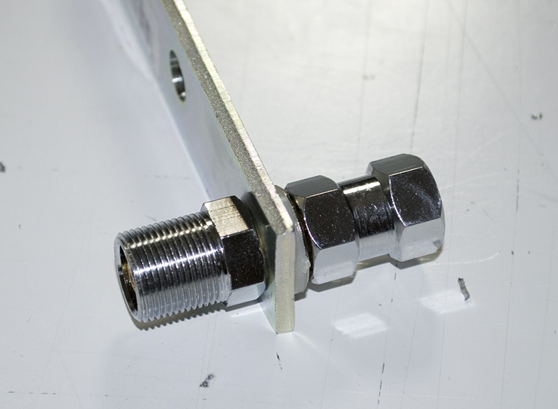 Assemble the antenna mount using the 1/2″ hole drilled in the L-bracket.
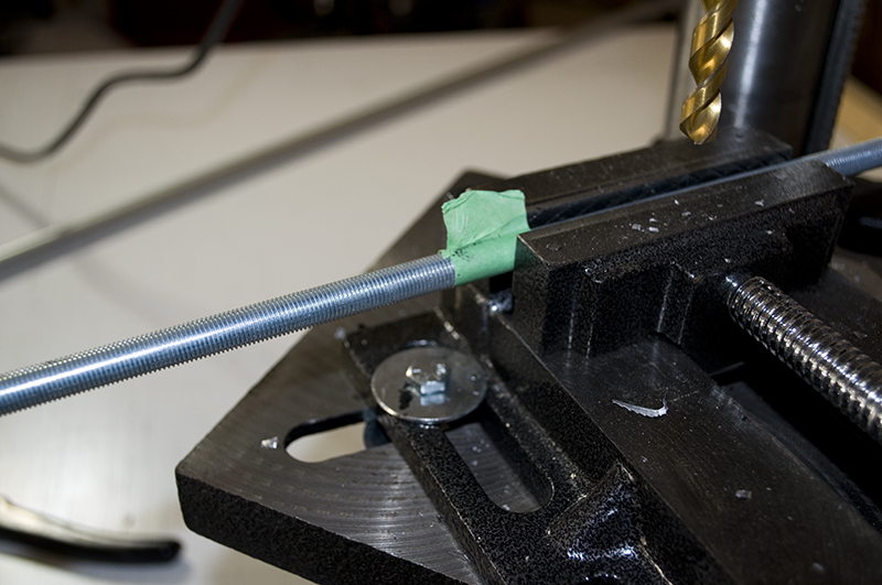 Cut the long and short elements from opposite ends of the 3/8″-24 threaded rod by clamping the middle portion (which will not be used, so any possible damage to the threads is not a concern) in a vise and cutting with a reciprocating saw, or use a band saw or hacksaw. To calculate the lengths for the elements, I used the calculator at http://www.hamuniverse.com/jpole.html.
Depending on the 2 meter and 70cm frequencies you choose for tuning your antenna, you might have to compromise a little. I got lucky, because I was using 147.060 MHz and 442.100 MHz, which just happened to both yield a length of 19.08 inches for the longer of the two 3/8″ rod elements. It’s a good idea to cut the elements a bit longer than the calculation — you can trim a bit off to improve the tuning in a little while, but you sure can’t stretch them if they start out too short!
 3/8″ rod elements cut and attached to the bracket using two self-locking nuts on the short element, and one on the long element to tighten it down after threading it into the antenna mount.
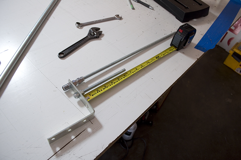
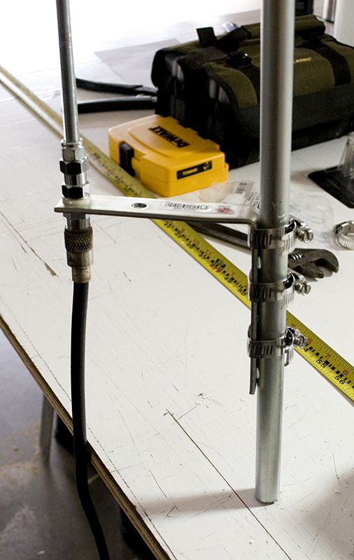
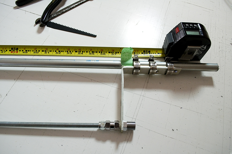 The antenna calculator (link showin in a previous step) indicated that the bases of the elements needed to be 57-1/2″ down from the top of the 1/2″ EMT conduit piece on my antenna. Cut your 1/2″ conduit 6″-7″ longer so that you can use the #12 hose clamps to attach the L-bracket physically (and electrically) to it. You might also need to slide the bracket with the two elements up or down to fine tune, so leave yourself some room for adjusting.
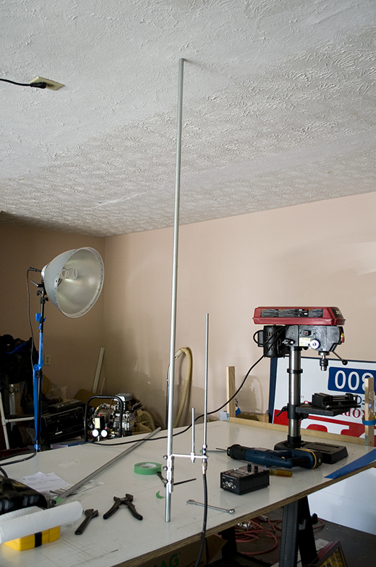 Antenna assembled and coax attached. By pure luck, my antenna just happened to be the right length to wedge between the top of my workbench and the ceiling of the garage. It needs to be standing upright for initial tuning.
 Remove the short element and tune for resonance, proper SWR and impedance on the 2 meter frequency first.
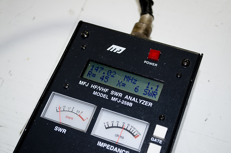 Using an antenna analyzer, I was able to tune my antenna to 1.1:1 SWR and an impedance of 45 ohms at a frequency of 147.02 MHz. I was shooting for 147.06 MHz, but the setting knob on most analyzers can be really touchy, so this was close enough for me. I did have to trim a little off the longer 3/8″ rod to optimize the tuning, but that’s why you start a bit long and trim down to tune. You might also need to slide the bracket with the two elements up or down a bit for optimum tuning and performance.
Next, reattach the short element and tune/trim it for best SWR and impedance at the chosen 70cm band. I did not have access to an analyzer for 70cm, so what I did was calculate what percentage of the “calculated” length the longer of the two 3/8″ rod elements turned out to be when best tuned, which was 95%, and used the self-locking nuts to have the shorter 3/8″ element sticking up above the L-bracket to 95% of its originally calculated length. Include the locking nut that’s above the bracket in the measurement. Optimally, you should adjust it with an antenna analyzer.
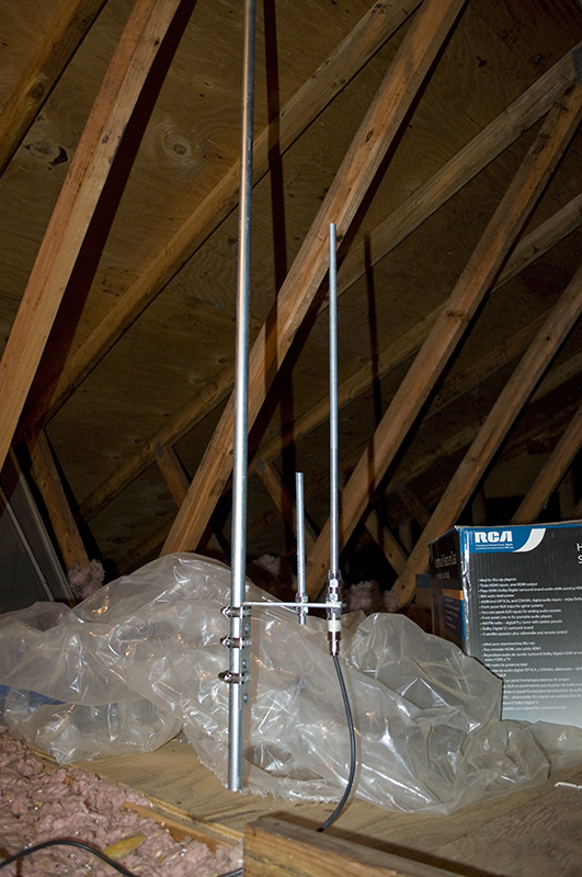 I mounted my antenna in my attic by using a conduit clamp and two screws to suspend it from a truss. Then I used the analyzer to re-check the tuning, because nearby objects can affect the tuning. It turned out that I still had 1.1:1 SWR and 46 ohms of resistance at the other end of my coax.
Then, the big test: how well does it actually work?
Answer: incredibly well. I am getting into 70 cm repeaters I could not hit before, and it’s working equally well on 2 meter repeaters. In fact, I am hitting 2 meter repeaters at least 60 miles away with only 5 Watts of power, and 70 cm repeaters 30 miles or more away with the same amount of power. In terms of 2 meter performance, it appears to be working better than my Ringo Ranger II, which is mounted outdoors with the tip about 35-40′ up in the air (FYI, the Ranger II has an estimated gain of 7+ db.) To make a long story short, this thing works even better than I had hoped for. Not too bad for an antenna that cost roughly $35 to make and took about an hour to actually build and tune.
— Footnote as of 9/19/13 —
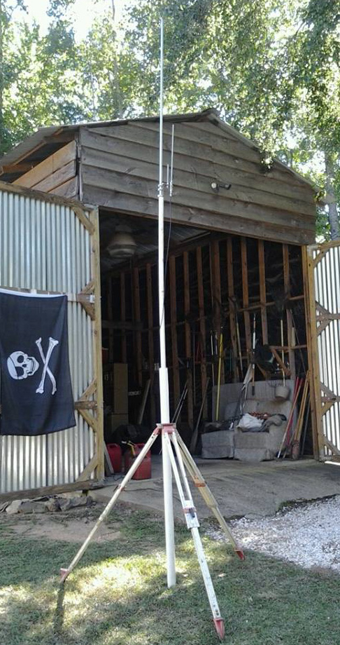 I have removed the antenna from the attic and started playing with it as an emergency field antenna using a contractor’s level tripod and some PVC pipe. Set up as seen in this photo takes about 1 minute for one person to set up, and about 15 seconds to completely disassemble. It will easily fit in a trunk, behind a truck seat, etc.
We *finally* threw an MFJ-269 Analyzer on the thing so that we could accurately read the 440 band performance on it. 1.5:1 or better across the entire band (and well below the band and above, for that matter.) Testing on and around the 2 Meter band showed 1.2:1 or better across the entire band, and 1.5:1 or better from around 135 MHz through approximately 165 MHz — definitely more than adequate for Amateur Radio or even Public Safety use.
~ 73’s from KK4ICE
Hi Dan;
Built the dual band and it tuned and worked great. Also built a 1.25 meter on the same design. Now I’m trying to combine the three.
Thanks
Neil
WW5NX