I have received numerous requests for detailed instructions and information on how I converted the Yaesu DR-1X Fusion repeater to a repeater capable of doing DMR, D-Star, C4FM (Fusion), P25, NXDN, or any combination of these digital modes by using Scott Zimmerman’s excellent and powerful STM32_DVM board running on a Raspberry Pi with the Pi-Star software. My interfacing method is somewhat of a hybrid of other document methods you can find on the web; however…
So how is my interfacing method and diagram different from other information you can find on the internet?
This interfacing conversion method solves the low transmit modulation problem many users have encountered when trying to use external repeater controllers and devices with DR-1 or DR-1X repeaters.
- Disclaimer: non-factory modifications of the DR-1 or DR-1X repeater will most likely void the factory warranty. If you undertake the following (or any non-factory) modifications of the repeater, you are doing so at your own risk. No warranty or liability of any kind is expressed or implied on my part or anyone else’s if you choose to perform these or any other modifications to your repeater.
The instructions and diagram in this document will take you through the steps of not only creating an interface for the STM32_DVM DMR modem/controller board, but will

STM32_DVM running on Raspberry Pi2 with optional case installed, connected to my custom interfacing cable for the Yaesu Fusion DR-1 and DR-1X repeater.
also provide you with an interface which is flexible enough to provide interfacing for other controllers and devices, and can be quickly and easily disabled, essentially returning the DR-1 or DR-1X to operating just like it did from the factory (analog or C4FM modes with the internal controller functioning as though no modifications have been made to the repeater.)
In the event you ever need or want to use the repeater just like it came from the factory, you can very easily do so. The DR-1X which I used for converting my coordinated repeater from analog FM to a DMR machine is one of the early DR-1’s which we long ago designated as a spare/emergency repeater in the event one of our
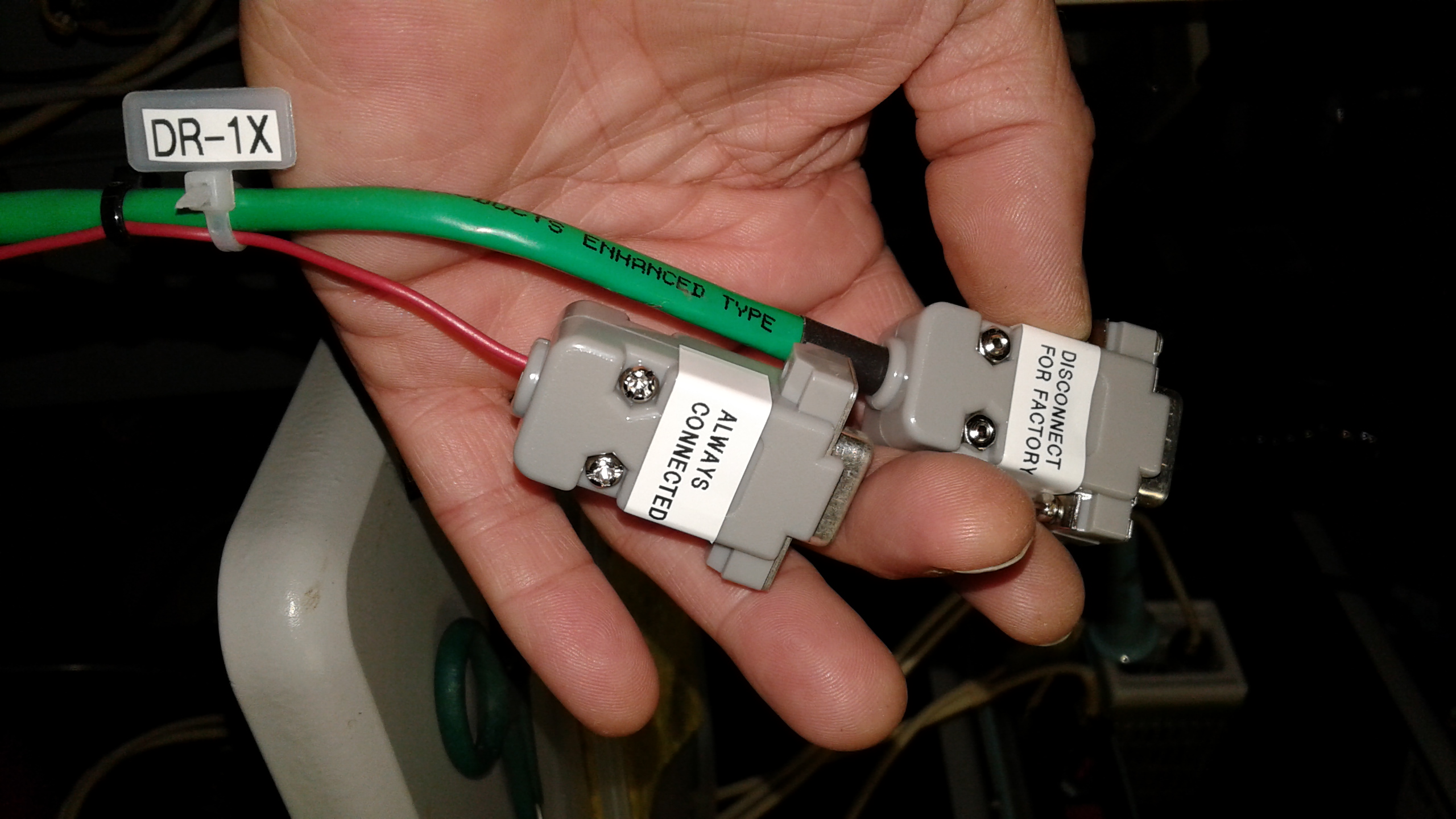
DR-1 or DR-1X connection end of my custom interface cable for the STM32_DVM.
2-Meter or 70cm analog machines failed. If we absolutely need to use it for that purpose, we can easily do so and it will only take a minute or two have the machine ready for that in an “unconverted” fashion, so to speak.
So, let’s get started!
The first step to making all this work (in a flexible way which allows reverting the repeater to “out of the box” operation if needed), involves doing a little internal modification to a cable inside the DR-1/DR-1X which gives you the ability to make some things work which don’t really work without the modification. For the very first step, I will refer you to the website of Doug Crompton (WA3DSP), who is well known and respected among hams — especially those of us who found ourselves looking for ways to add AllStar nodes and external controllers to these Yaesu repeaters and have it actually WORK!
- Before I refer you to a page with the instructions for the first step, please note:
- I recommend you follow Doug Crompton’s instructions for the cabling modification for the DR-1X, but you can stop when you get down to the section with the heading “UPDATE.” Also, note that I opted to use a 9-PIN SUB(D) connector, whereas Doug used a 25-PIN connector. You can do it either way, but a 9-PIN will provide you all the connections needed and is a less bulky and slightly less expensive connector.
Doug Crompton’s well documented instructions for modifying the DR-1X repeater show you how to cut and do a breakout of the USB/DIN cable which runs between the receive radio and the transmit radio in the DR-1 or DR-1X. The reason you need to do this, as Doug notes, is that this factory installed cable between the two FTM-400 radios used in the DR-1X repeaters contains two wires which often prevent external controllers simply wired to the 15-pin “I/O” interface on the back of the repeater from working as you’d think they would. As built and wired from the factory:
- One of the two wires (the YELLOW wire) inside that USB/DIN cable directly connects the COS from the Rx radio to the PTT of the Tx radio.
- Another wire (the RED wire) inside that cable directly connects the Rx audio output from the Rx radio to the Tx audio input of the Tx radio.
For factory intended operation, the above two “direct” connections are not an issue; however, in order to make most external repeater controllers and devices work as they are supposed to and actually control the radios, those lines need to be cut and a “breakout” connector added which allows you to route the COS, Rx Audio, PTT, and Tx audio lines to the external controller/device without them being internally bridged in the repeater. Doug’s instructions show you how to do that very nicely. Once you’ve followed his instructions and created an external connector with access to those lines/signals, returning to this page will take you through the rest of the steps needed to making the DR-1X one of the most flexible multi-mode repeaters on the market. In my humble opinion, what you will be doing is the ultimate upgrade and modification to the DR-1X, short of trading it in toward a DR-2X machine. In fact, I think this modification is even better, for a couple of reasons:
- Even if you went so far as to trade-up for DR-2X, you would still have a repeater designed to do only analog or C4FM digital; whereas, this modification makes the repeater ready to operate in any the following digital modes (or any combination of them) when used with the STM32_DVM from Zimmerman:
- D-Star
- DMR
- C4FM/Fusion
- P25
- NXDN
- To date, I have not found anyone who has managed to make any of the MMDVM type devices designed for digital radio modem and codec purposes actually work with the DR-2X. It appears that either Yaesu put some effort into preventing folks from pulling that trick off, or they simply didn’t consider that important enough to make provisions for it. Either way, if you have a DR-1X, users worldwide are saying “Don’t trade it for a DR-2X if you plan to use something like one of the MMDVM type devices — you won’t be able to make it work like you can with the DR-1X, resulting in an expensive ‘oops’ and a repeater that’s actually more limited than the DR-1X in a critical way.” [paraphrasing, but that’s the meaning.]
Creating the custom cabling harness you’ll need for hooking the STM32_DVM up to the DR-1X repeater and being able to revert to factory configuration of the DR-1X if desired or needed.
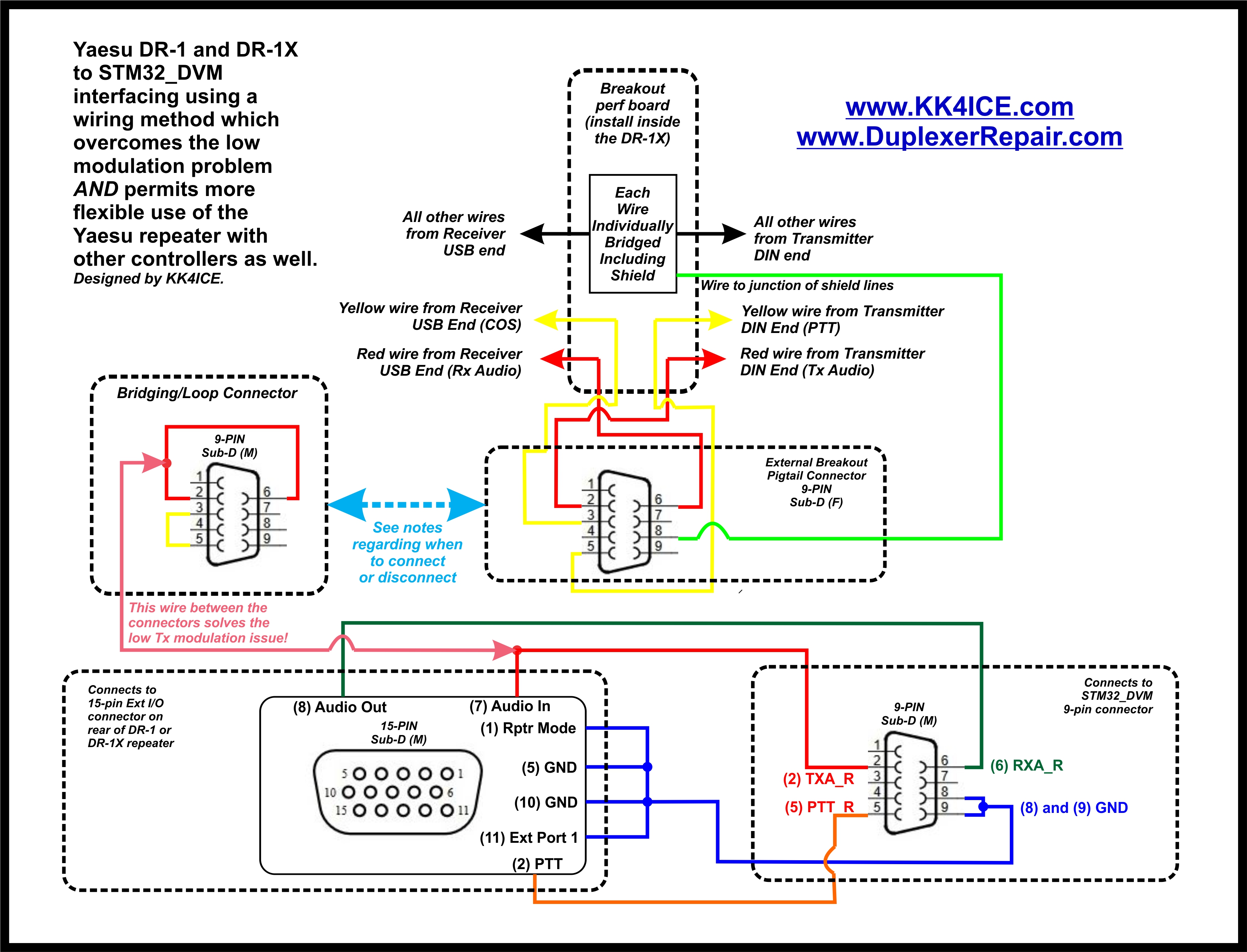 Here is the diagram of the whole wiring scheme. You can download/open a JPG version of this diagram for larger viewing, or a PDF version if you prefer.
At the top, center of the diagram, you will see the “Breakout” cabling portion) enclosed in a dashed rectangle) which is the part of the conversion which Doug Crompton’s instructions (above) had you perform. As you can see, the COS, PTT, Rx audio, and Tx audio lines are now all separated out and accessible at the 9-PIN female connector you added in “pigtail” fashion (or a 25-pin, if you chose to use that instead, in Doug’s fashion.)
Once you have built your interface harness, here is how you will utilize it for interfacing to and using the STM32_DVM
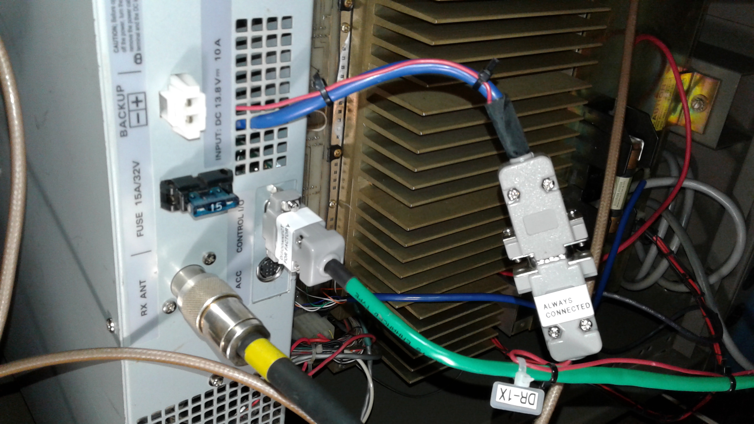
STM32_DVM to DR-1X I/F cable connected at repeater-end.
With the harness connected to the STM32_DVM’s 9-PIN connector, the 15-PIN “I/O” connector on the back of the DR-1 or DR-1X, and the 9-PIN male Bridging/Loop connector plugged into the female connector of the pigtail you’d created and added per Crompton’s instructions, you’ll simply need to set the transmit and receive frequencies
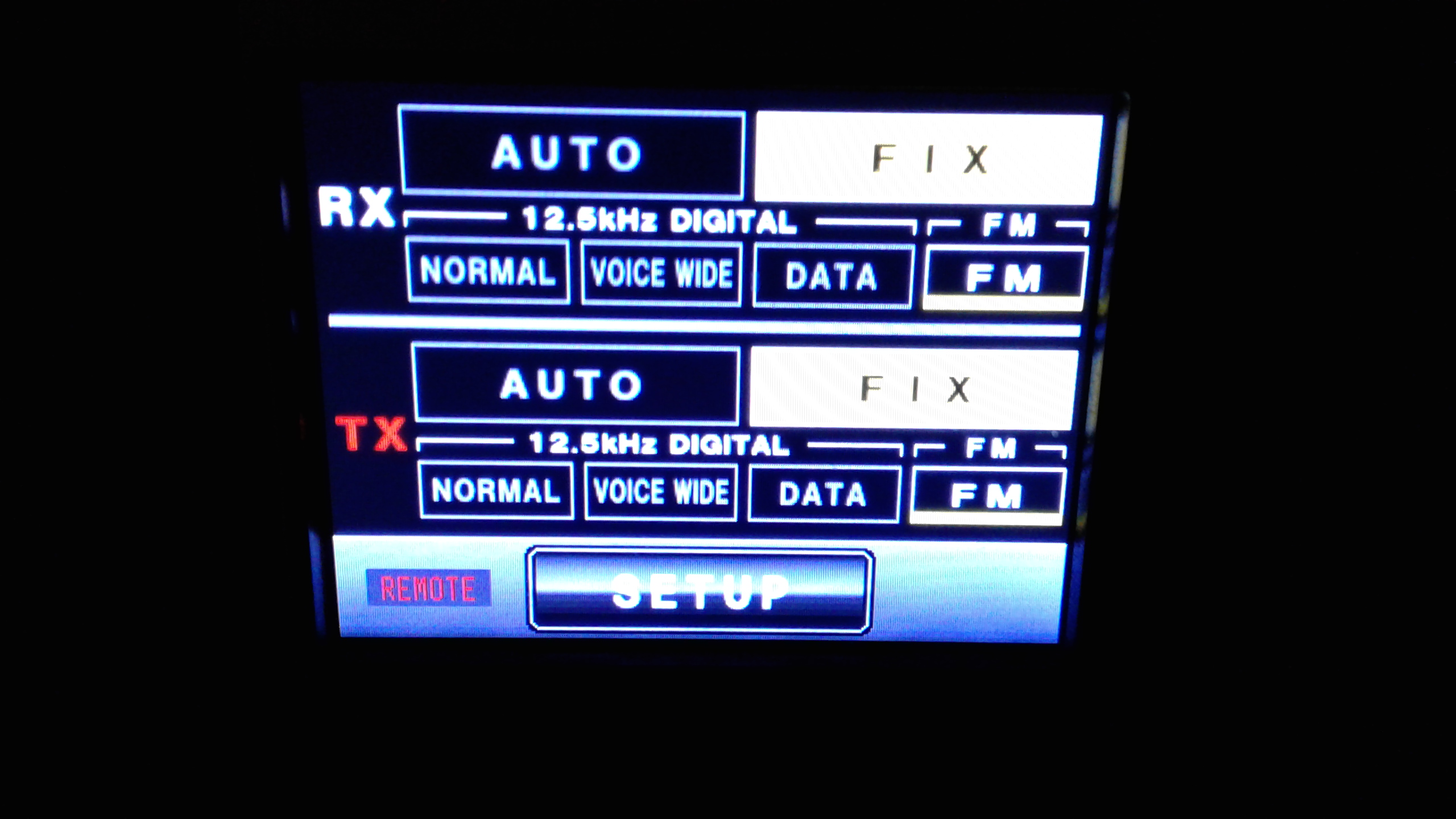
With the 15-pin cable I created for interfacing the STM32_DVM to the DR-1 repeater plugged in, the repeater is forced into “remote” mode and fixed FM input and output. The STM32_DVM actually does the DMR decoding and encoding, and the limited digital functions of the Fusion repeater are totally bypasses. With the STM32_DVM interfaced to the Fusion repeater in this fashion, the repeater actually becomes capable of functioning as a DMR, C4FM, D-Star, P25, or NXDN repeater, and can even operate in a combination of those modes — a HUGE improvement in capabilities for the DR-1 and DR-1X repeaters!
via the front touchscreen panel of the repeater (Yaesu uses the terminology “Downlink” and “Uplink,” as you probably know already.) You will also need to set the transmit power level (low, mid, or high) using the DR-1/DR-1X touchscreen.) Those should be the only settings you need to adjust. You’ll notice that with this harness connected, the repeater is forced into “Remote” operation mode and that it is also forced into Analog FM receive and transmit. You can not use the front panel of the DR-1/DR-1X to change any of those settings — it simply will not let you do so. That’s because your harness bridges pins 11 and and 1 of the repeater’s “I/O” port to ground, forcing it into that mode and locking out the ability to accidentally change the operating mode. If you power cycle the repeater (or in the event of power interruption) the repeater will automatically boot up in this setup, so there’s no need to worry about what happens with the machine in the event of a restart. Your STM32_DVM board and the RPi running Pi-Star should also boot/restart in whatever settings you have it set to operate at, so if the power fails at the site, everything should theoretically be back up and running with your repeater reconnected to whatever DMR server(s) you utilize in your setup in just a couple of minutes at most when the power is restored, assuming your ISP and internet router fire are working or come back online.
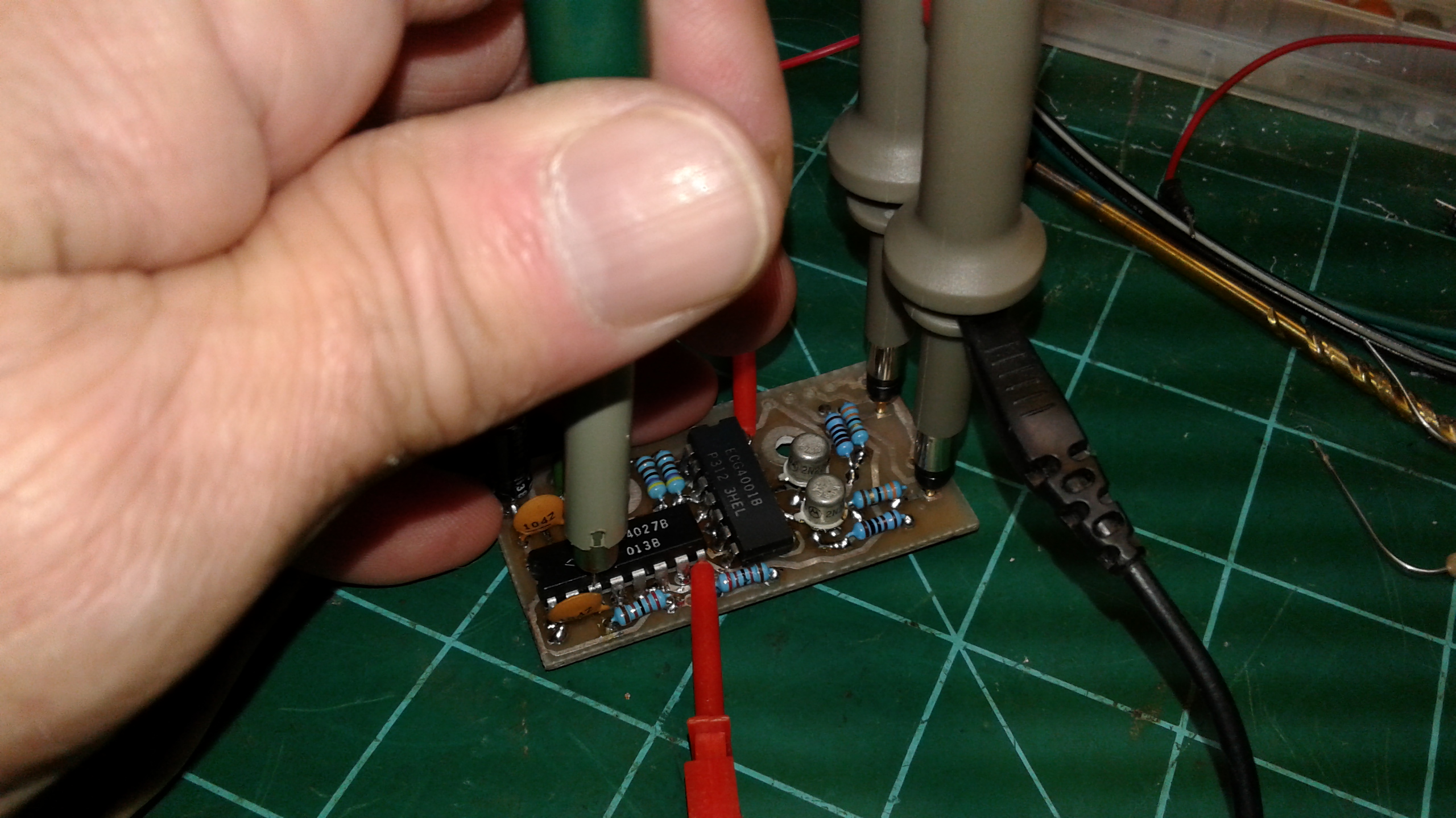
What makes my interface/cabling design different from all others I found on the internet as that wire you see indicated in pink which ties to the Rx/Tx Audio line inside the repeater. All of the information and instructions I have seen on the web for connecting external controllers to the DR-1X show the Tx audio routing from the external controller being connected to pin-7 of the external “I/O” connector on the repeater. That pin apparently does NOT go directly into the transmit radio’s Audio Tx connection — rather, it appears that pin actually goes through some signal processing (and DSP) circuitry included in the internal controller. It appears that if you just connect your Tx Audio signal to that pin, it’s very likely to be attenuated by that circuitry before getting routed to the transmit-side radio in the repeater, which would explain why so many people have reported inability to get proper modulation from the Tx radio. In the case of my build, despite the fact that Zimmerman designed his board so that it can produce up to 5 volts P-P of transmit audio, the radio would only modulate to around 0.5 KHz max when I just fed the Tx audio to that pin on the “I/O” port of the repeater. After thinking and studying the situation for a while, I decided to try taking the Tx audio from the STM32_DVM to that Rx/TX audio line access point which is readily available at the Bridging/Loop Connector and pigtail. Voila! The transmit was suddenly way overmodulated.
- A helpful and recommended suggestion: looking at the wiring of the Bridging/Loop Connector 9-PIN male plug on your harness, if you will make yourself up a similar 9-PIN male plug with the same wiring (pin-2 bridged to pin-6, and pin-3 bridged to pin-5, but WITHOUT the external wire which would go bridge to pin-7 of the 15-pin plug (indicated in pink color on the diagram)) you will be able to completely remove your STM32_DVM to DR-1X cabling harness and insert the spare “Bridging/Loop Connector.” This will permit using the harness and STM32_DVM on another machine, without the need to leave it connected to the repeater in order for the COS/PTT and Rx Audio/Tx Audio to be bridged for factory operation, tying up your harness cable.
When you are using the STM32_DVM, RPi, Pi-Star combination attached to the repeater, the repeater’s analog CW ID will be controlled and generated by the external hardware. The ID settings in the internal controller of the DR-1 or DR-1X will be ignored. In addition, hangtimes, etc. will actually become functions of the external hardware and software. That’s why the only settings you’ll need to worry about in terms of the repeater’s internal controller when using this setup for digital operation are the radio frequencies and the transmit power level.
Reverting to factory operation in order to use the repeater with internal control, just like nothing had ever been modified) you will simply do the following:
- Power-down the repeater and the RPi/STM32_DVM equipment
- Disconnect the 15-pin cable of your harness from the “I/O” port on the back of the repeater
- Disconnect the STM32_DVM 9-pin male plug of your harness from the connection to the STM32_DVM board
- Leave the 9-PIN male plug of your harness which connects to the Crompton-style pigtail connected. This leaves the COS/PTT and Rx/Tx Audio lines bridged the way they were in the factory cable. OR:
- If you built a spare Bridging/Loop Connector (9-PIN male) as I suggested, you will connect it to the 9-PIN female connector on that Crompton-style pigtail interface cable in place of the one from your STM32_DVM interface harness. Now you have a factory-functioning DR-1 or DR-1X and you can use your STM32_DVM setup and harness on another machine if you want to.
- Power the DR-1 or DR-1X back up and check and adjust the settings for the repeater’s internal controller as desired using the front touchscreen panel of the repeater.
- If you built a spare Bridging/Loop Connector (9-PIN male) as I suggested, you will connect it to the 9-PIN female connector on that Crompton-style pigtail interface cable. Now you have a factory-functioning DR-1 or DR-1X and you can use your STM32_DVM setup and harness on another machine if you want to.
Herein lies the other advantage and extended usability of this whole setup…
Let’s imaging you want to interface an external repeater controller to your DR-1/DR-1X. That pigtail you created in the first step can become the key to making it happen successfully. Disconnecting the Bridging/Loop Connector plug from your harness (or the “spare” one you built for factory operation without the harness) from the pigtail provides you with fast access to the needed COS, PTT, Rx Audio, and Tx Audio ports on the two radios with the bridging directly from one radio to the other removed. You would still likely need to built a 15-pin male connector wired to some of the signals on that “I/O” port on the repeater (most likely you’d need to bridge pins 1, 5, 10, and 11 together inside a 15-pin male plug in order to truly force the repeater into external/remote operation and lock out the ability to intentionally or accidentally put the repeater’s internal controller into any mode which could cause issues.)
- Sort of a side-note but important information for anyone who might not be all that familiar with using external controllers and devices with the DR-1/DR-1X:
- When using external repeater controllers and devices such as the STM32_DVM or other MMDVM type devices with the Fusion DR-1 and DR-1X repeaters, a serious logic flaw exists in the machine which can destroy your PA (not to mention your day.) If someone tries to send a digital signal (such as C4FM signal) into the repeater and the internal controller tries to handle it, a logic glitch can cause the repeater to lock-up in transmit mode. This has happened to many owners of these repeaters when using external controllers with the machine. It will not drop transmit on its own if that happens. It won’t time out. There is no remote “knockdown” ability. It will stay in transmit until the user can get to the repeater and kill the power, or until the PA melts down — whichever comes first. Either way, it ain’t a good day in Hamland if that happens. This is why it is so critical to have those four pins (1, 5, 10, and 11 on the 15-pin “I/O” port bridged together when using an external controller on the DR-1 or DR-1X — it locks the repeater into “remote” (external control) mode and keeps the controller from inadvertently trying to key the transmitter on its own and, thus, from causing the repeater to get stuck in transmit due to that logic issue.
Recent Comments