This post is a combination of a review of the MiniVNA Tiny analyzer and the results of using it to test another set of 6 Meter, 3 Element beams I built. I recently added the new MiniVNA Tiny to my lineup of tools here in the KK4ICE shack and workshop. I must say that I am beyond pleased with this nifty little device. With its ability to perform a myriad of antenna and filter tests from HF all the way up to 3.3 GHz (continuously), it more than easily replaces all the previous portable antenna analyzers in my toolkit — and then some. Plus, it does things other things that those other handheld and portable analyzers can’t or don’t do, such as a highly stable and accurate signal generator mode, a beacon mode with several nice features including easily programmable CW beacon message, and a host of other functions. Before purchasing my MiniVNA Tiny, I had a few questions about the device, which I must say that Ralph at http://www.w4rt.com was very quick and courteous to respond to in excellent fashion.

The MiniVNA Tiny is appropriately named. As you can see in the photos, it’s small. But it packs a lot of functions in a little box that can easily fit in your shirt pocket with room to spare. The unit requires no batteries, drawing its operating power right from the USB connection to a computer. Okay, so carrying around a laptop means the setup for testing antennas and filters isn’t quite so tiny in the end, but take my word for it: it’s well worth carrying around a laptop in order to use the MiniVNA Tiny. You can also power and operate it with an Android tablet using the freely downloadable Android app called “BlueVNA,” provided the USB port is capable of driving a high-powered device — the Tiny does require quite a bit of juice in order to do its job. You just need an On-The-Go (OTG) adapter for your Android device in order to be able to connect the Tiny as a peripheral device. My Samsung 10.1 Tab wasn’t able to provide quite enough power through the port to keep the Tiny awake. I’m working on a way to use rechargeable AA batteries and a USB hub to resolve that issue.
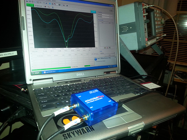 The Tiny has two SMA connectors, labeled “DUT” and “DET.” For tests using the reflection mode, you only have to utilize the DUT port. The Tiny serves as the signal generator, spectrum analyzer, and return loss bridge (RLB) all in one package that isn’t much larger than just a decent RLB alone. For doing transmission mode tests (such as coaxial cable losses, duplexer cavity tests to fine tune the reject notches, and some other tests) you’ll also use the DET port, with it serving as the return input from the coax, filter cavities, etc. Just by the way: the Tiny proved to be quite accurate when I gave it a trial run of its coax length/distance-to-fault measuring function. This function, along with all of the other tests mentioned in this article were performed using the latest version of the Windows based program “VNA/J” to run the Tiny. The freely downloadable software and drivers for the device were a breeze to install, taking me only about 15 minutes to download, install, and even run the calibrations for the Tiny. Links and info for the software and drivers are on the Mini Radio Solutions website. It comes with open, short, and load SMA reference loads for performing the reflected mode calibrations, and you’ll simply need to connect a loop between the DUT and DET ports for the transmission mode calibration. There’s also a frequency calibration which is quickly and easily performed by connecting the Tiny to a known accurate frequency counter or other device. In my case, I just ran it into my IFR 1600 and quickly calibrated it to within 1.0 Hz of the IFR’s readout.
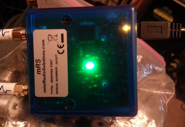 There are two LED’s visible through the case on the reverse side of the Tiny. The green LED indicates that there is power getting to the device via the USB cable. The yellow LED near the USB connection lights up when data is flowing between the Tiny and the computer. There are no switches, controls, or anything to worry about with the Tiny, with perhaps one suggestion I’ll throw out there for anyone considering purchasing a Tiny: get yourself a couple of SMA to SO-239 cables and keep them attached to the Tiny. This is sort of an expensive little box to be messing around with the built-in SMA connectors more than you have to, in my opinion. Male SMA to female SO-239 pigtails are pretty cheap and readily available. That’s about a $10 investment that could keep you from damaging a $579 device unnecessarily.
So, what did the MiniVNA Tiny have to say about my other set of homemade 6 Meter beams, which I had not yet fully tested? The Tiny can export test results in a myriad of formats, including detailed PDF files, JPG images, CSV files, and export files compatible with numerous other programs that many hams use for in-depth antenna, filter, and transmission line work. For our discussion, here is a JPG export right from the VNA/J software running the Tiny (you can click on the image to open it in a larger version).
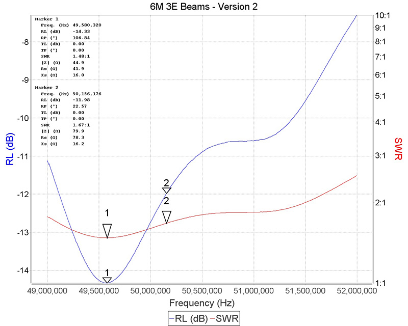 My goal in building the beams was primarily for use on the 6 Meter “Buzzard Net,” which is operated by the LaGrange, GA Amateur Radio Club on Monday evenings. The Buzzard Net usually operates on 50.155 MHz USB. According to the Tiny, the antenna is resonant at 49.580 MHz, showing a Return Loss of 14.33 dB (indicated by marker #1.) The blue line on the graph indicates the measured return loss. The red line shows the SWR, which is 1.48:1 for these beams at 49.580 MHz (also indicated by a marker labeled “1”). A bit of an aside here to mention another great feature of the Tiny: when running the return loss and SWR tests, a couple of quick mouse clicks are all it takes to have the software and the Tiny find the minimum or maximum return loss, SWR, etc. within the traced test results. No more interpolating (or guessing) — it nails it down in a fraction of a second. To place a second marker (marker #2 in the test above) you simply hold down the shift key while moving the mouse pointer to a second frequency you want specific data for and click. In fact, the software allows you to set multiple markers, which I have found very helpful. I dropped marker #2 at 50,156,176 Hz (50.156176) MHz, which is right on my desired frequency of 50.155 MHz. Accuracy down to the 1 Hz digit ain’t exactly a feature of the lesser-expensive consumer/ham-grade analyzers that the vast majority of amateur radio enthusiasts are accustomed to buying (and repairing or sending off for repair, constantly replacing, etc.) While the $579 price tag for the Tiny might initially raise the eyebrows of many a ham radio operator, when you consider the fact that one MiniVNA Tiny will do what it typically takes multiple analyzers from other manufacturers to perform (due to their limited frequency ranges, gaps in band coverage, etc.), and it can even replace a spectrum analyzer/tracking generator and return loss bridge (big $$$ if you invest in those), plus you don’t have to keep buying expensive packages of batteries for the Tiny, since it just gets it power from the computer, and suddenly the investment in the Tiny starts to make seriously good sense. So, back to the test results and what I discovered about these 6 meter beams.
Looking again at the test results with 50.155 MHz in mind, the test results tell me that I have a return loss of 11.98 and an SWR of 1.67:1 at 50.156176 MHz. It also tells me that the impedance seen at the rig (antenna and transmission line effects included) is Z=79.9 — not the ideal 50 Ohm load we want to see. That’s not really surprising, as adding parasitic elements to a dipole, which is what the beams boil down to, always causes interesting things to occur with the antenna’s impedance. There are various ways the impedance can be corrected, including gamma and delta matches, but those can be time consuming and bit expensive to build, not to mention them being subject to trouble down the road due to being exposed to the elements. Using the stub method to match the antenna/load is the option I’ll go with for these beams. Using a very handy online single-stub match calculator available at http://www.arcticpeak.com/antennapages/single_stub_match.html and plugging in the values of the frequency (50.156 MHz), the desired impedance of 50 Ohms, the measured R value of 78.3 Ohms, and the measured reactance value of X=16.2, the calculator tells me that I need to insert a Tee-connector 0.386 Meters from the antenna and add a matching stub of either 0.326 Meters (for a shorted stub) or 0.076 Meters (for an open stub) and voila: I’ll have a load of 50 ohms with no reactance. Oh, another aside on the Tiny here: the MiniVNA Tiny and VNA/J software combination gives you test results with the true sign of the reactance — no more horsing around trying to figure out whether the reactance is negative (capacitive) or positive (inductive). Most ham grade antenna analyzers can’t give you the true sign of the reactance. Even worse, many can’t calculate the numeric reactance (X) value unless the antenna is already close to being a perfect match to begin with. Some simply don’t include reactance measurement at all. There simply is no substitute for knowing the reactance value and its true sign, unless you just get a thrill out of using the W.A.G. method of cut… measure… cut… measure… toss it and cut another couple of pieces of coax and solder some more PL-259’s… measure… cut… cuss… repeat ad nauseum until you finally just decide to live with a mismatched antenna and go have a cold one while you operate your rig with a weak performing antenna that you spent hours constructing (not to mention $$$). With the MiniVNA Tiny, you can get the match and load right the first time and enjoy the benefits of full power output and transfer from your rig to the antenna.
By the way, have I mentioned that I really do like the MiniVNA Tiny?
~ 73 from KK4ICE.
Recent Comments