A friend brought a Kenwood IF-232C Serial Port Interface to me a while back asking for a little assistance with repairing it. He had replaced multiple components in it but it still wasn’t working properly. When hooked up to a Kenwood TS-850 radio and a

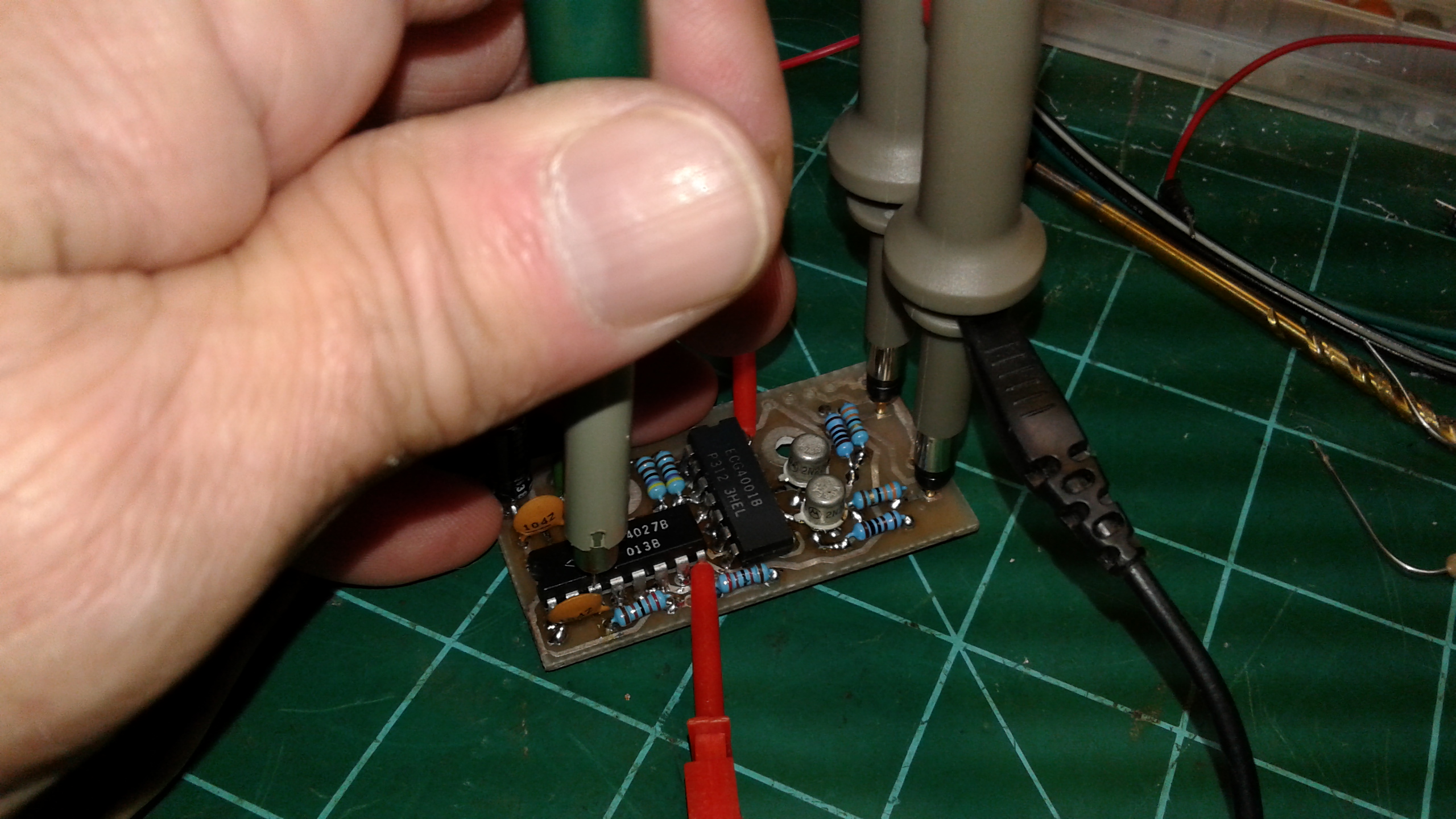
IF-232C on the bench, connected to a computer-based logic analyzer and an RS232 breakout box for logic and signal analysis.
computer, the computer could not communicate with the radio or control it. He had another IF-232C and it would work properly using all the same cables, radio, and computer. So he thought perhaps one of the logic IC’s was bad.
He purchased replacements for every DIP IC in the IF-232C. I removed all of the originals and replaced them, complete with the installation of DIP IC sockets for easier repair in the future should one of them fail. I did not have a radio or computer set up to use the IF-232C, so he took it back home only to discover it still would not allow his computer to communicate with the TS-850. So I decided to take another look at the unit and see what was happening. With the aid of a few specialized troubleshooting tools, I was able to figure out where the problem was and get the unit operating again in a matter of minutes. As it turned out, the replacement of all the IC’s was the correct choice of action — except I had overlooked something I had done during the repair which was in turn keeping it from functioning correctly.
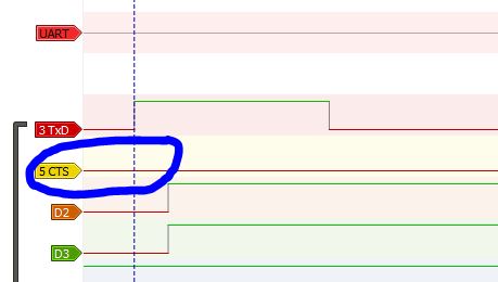
Logic analyzer connected to pins 3 and 5, as viewed using the Sigroc software at power-up. No activity seen on pin 5 (RTS.)
By using an RS232 breakout box, along with an 8-channel 24 MHz logic analyzer and Sigroc’s Pulseview software, I was quickly able to figure out what was happening. When the IF-232C is first powered on, pin #3 (TxD / Transmit Data) and pin #5 (RTS / Request To Send) should jump to a positive logic state then go low. Pin #3 was doing so; however, pin #5 (RTS) was never changing, as seen using an RS232 breakout box connected to the DB25 RS232 port on the IF-232C. This most likely meant either a faulty logic IC or a problem with the signal path going to pin 5 of the port. It only took a moment to pretty much figure out where to go to find the actual source of the problem.
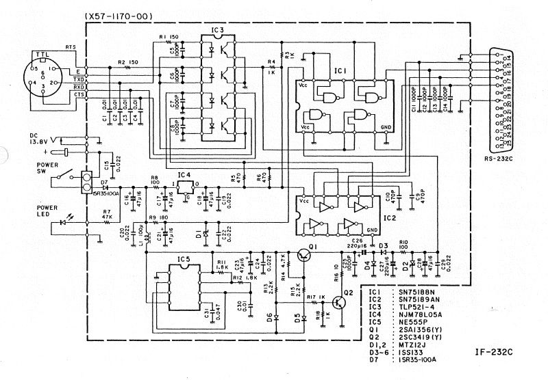
Kenwood IF-232C Schematic Diagram.
According to the schematic for the IF-232C, pin 5 of the RS232 connector is driven from pin 6 of IC1, a quad NAND gate (originally SN75188N, which I had replaced with an NTE75188.) I hooked analyzer probes up to pins 4 and 5 of the IC (both
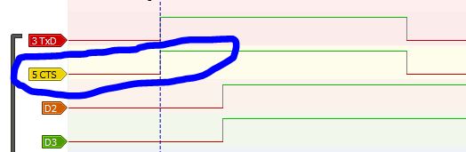
With the logic analyzer connected to pins 4, 5, and 6 of the IC it can be seen that the NAND gate is indeed working properly at power-up. The traces seen here in Sigroc Pulseview are pin 3 of the RS232 port (labeled as “3 TxD”), pin 6 of the IC (the output of the NAND gate, labeled as “5 CTS, which really should be “RTS” but that’s trivial given that I knew where and what I was looking at), and the two input pins (4 and 5) of the NAND gate (labeled as “D2” and “D3” in Pulseview.) Shortly after those inputs both go high, the gate output goes low (because it’s an inverting output gate, hence the “N” before the “AND” in the “NAND” designation.)
inputs to the second NAND gate on the chip) along with pin 6 (the output of the gate.) Voila! Both inputs were high resulting in a logic low output, and I could see the previously described high to low transition on power-up acting as it should. This meant something was broken in the signal path between pin 6 of the IC and pin 5 of the RS232 connector.
Upon removing the IF-232C’s circuit board from the chassis and inspecting the solder side, I instantly spotted the problem. During the replacement of the original IC’s in the unit and installing the sockets, part of the solder pad for pin 6 of IC1 had been damaged. With the pad gone, I had mistaken that pin for one of several IC solder pads in the unit which actually were not utilized, thus I had not repaired the trace. To correct this, I simply installed a small piece of
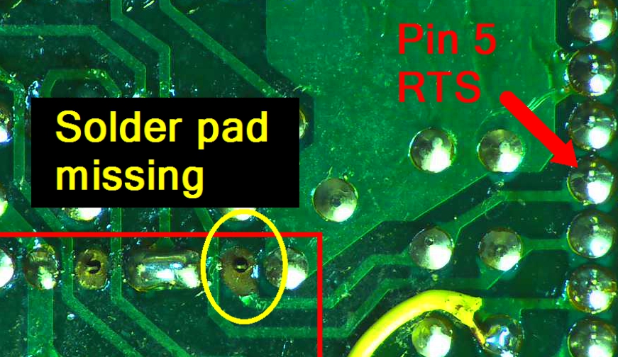
The source of the trouble: the damaged/missing solder pad and portion of the trace leaving pin 6 of IC1, eventually routing to pin 5 of the RS232 connector. My bad.
insulated wire as a jumper from pin 6 of the IC to the next component solder pad in the circuit. Upon reassembly and testing, everything worked great. Ham Radio Deluxe (HRD) running on the laptop has full control of the rig. The IF-232C basically functions to convert the logic voltage levels and invert them so that the PC and the Kenwood radio can communicate. The equipment is ready to go home to my buddy’s shack for his enjoyment.
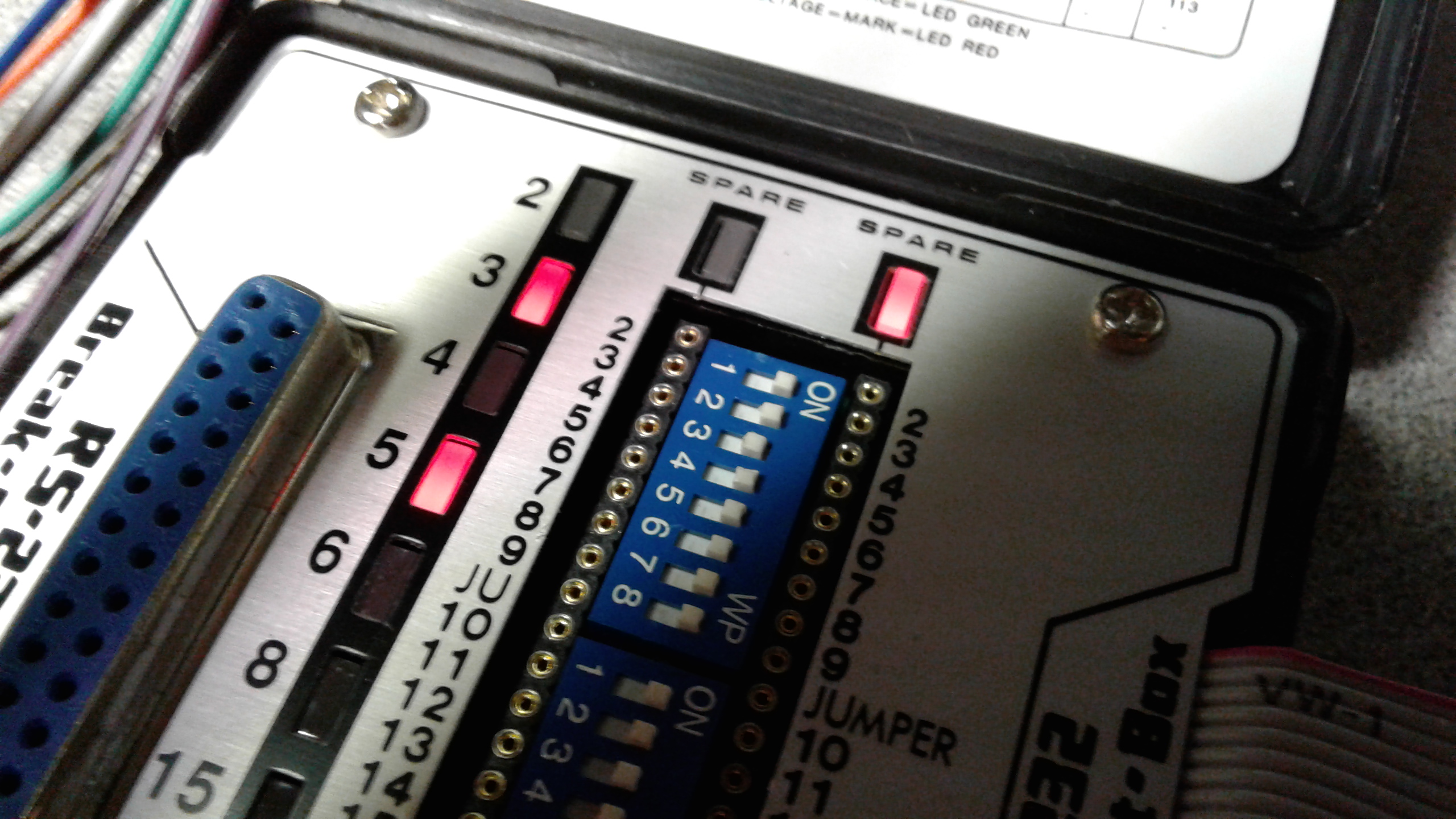
With a jumper/bridge wired to replace the missing pad and trace, on reassembly and power-up pin 5 (along with pin 3) of the RS232 connector switches to low almost instantly, as confirmed here with the breakout box. Done tater.
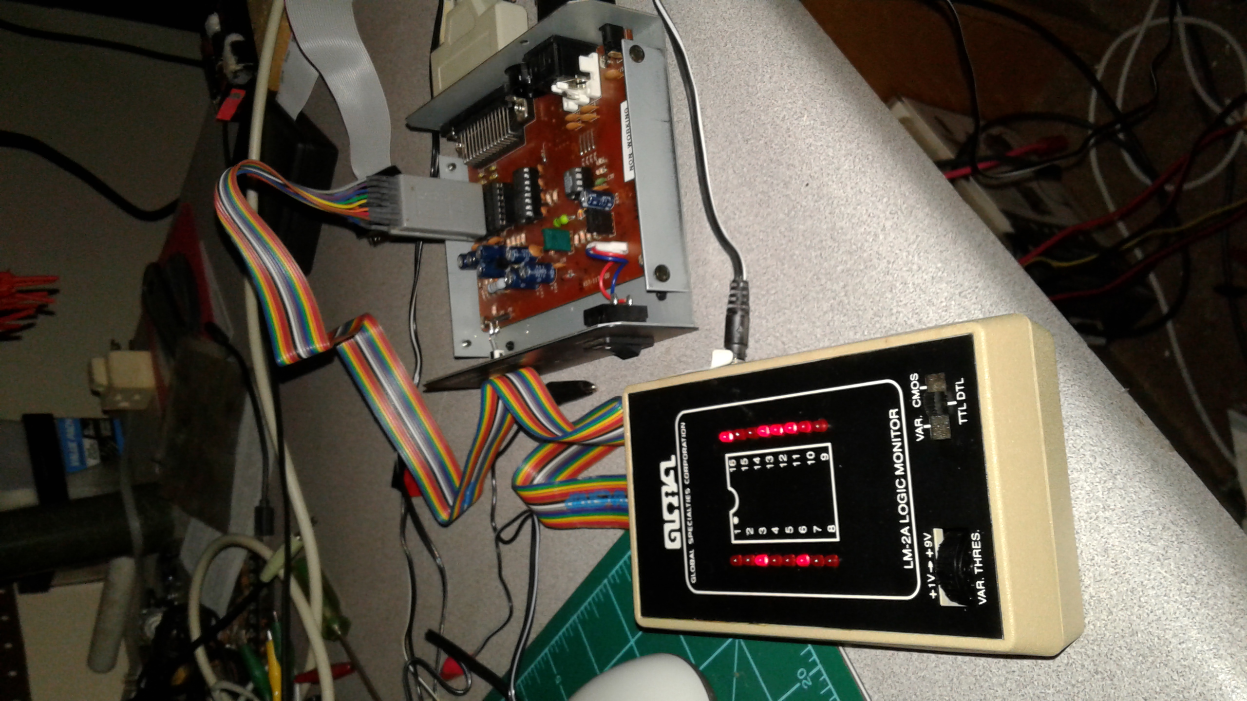
While I had the IF-232C opened up, I took the occasion to make sure the Global Specialties LM-2A Logic Analyzer was working as it should. The LM-2A simply uses a clip-on DIP style probe and LED’s to indicate the status of each pin. All those flashing lights can be darn near hypnotic 😉
Yep. Admittedly I make mistakes now and then during repairs. Armed with the right equipment, however, it’s a lot easier to figure out where the problem lies and get it straightened out.