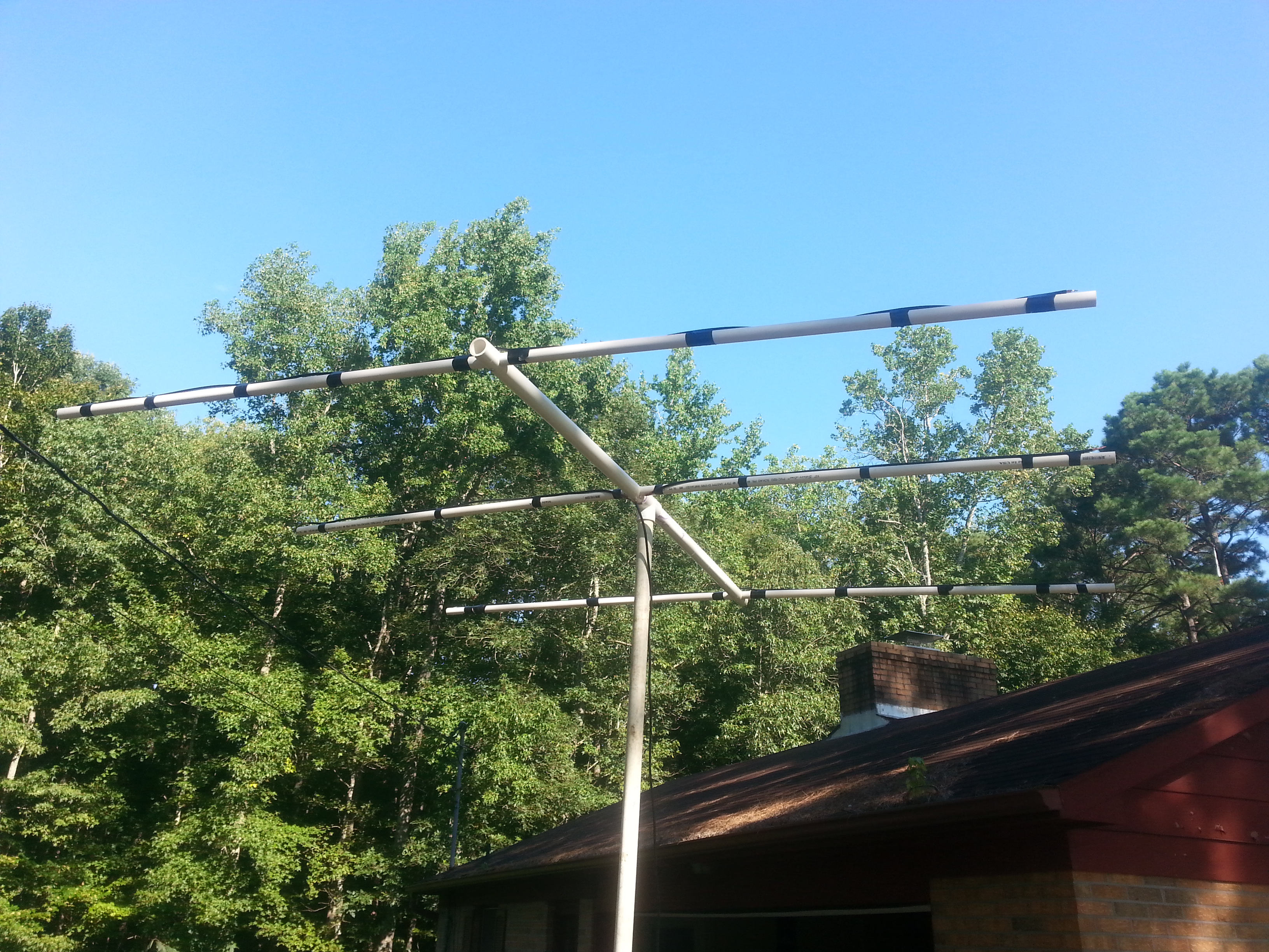
6-Meter, 3-Element beam ready for painting and mounting.
Having recently acquired an Icom IC-7200, I’m looking forward to getting involved in 6-Meter sideband again, particularly the LaGrange Amateur Radio Club’s “Buzzard Net.” I happen to be “Buzzard #56.” When I was participating in the Buzzard Net before, my reception was very marginal, as I did not have an antenna at the shack which was truly resonant on 6-Meters, so I decided to break out the tools and materials and build one — in true “ham fashion” (i.e., as absolutely cheap as possible.) I’m proud to say that I have it built, tuned, and ready for a coat of paint before permanent mounting. But it was not without an initial failed attempt, due to a difference in coax velocity factors.
The elements are shortened in comparison to typical 3-element beams at the same frequency by means of using coax with the outer ends stripped and the center conductor shorted to the shield in somewhat of a “Bazooka” antenna fashion. The driven element is split at the middle with the center conductor of the feedline connected to the center conductor of one side of the driven element, and the shield of the feedline connected to the center conductor of the other side of the driven element. The shield is left open/disconnected at the feedline attachment point. Thus, each half of the driven element is essentially folded back onto itself by means of the signal traveling down the center conductor and back along the shield until it encounters an open end connection near the feedpoint. The problem I bumped into was that the calculations used in the design I was attempting to copy were based on RG58/U coax with a velocity factor of 0.66 (a certain Belden cable.) When I made my first go at constructing the antenna, it turned out to be resonant around 63 MHz. OOPS! It’s really hard to stretch coax. Don’t ya hate it when that happens? So, I went and researched the specs on the JSC 3170 RG58/U cable I was using and found that it has a velocity factor of 0.78. Since I already had an antenna constructed which was resonating at 63 MHz, I decided to reverse-engineer the formula for calculating the element length and have another go at it. With the derived constant (K) of 4,561.2 which I came up with using the 0.78 Velocity Factor, I ended up with the following formula for calculating the overall length for the driven element:
L = 4,561.2 / F * 0.78
Where L=Driven element length (in inches), and
F=desired frequency (in MHz.)
Therefore, since I wanted the antenna to be resonant at 50.155 MHz,
L=4,561.2/50.155 x 0.78
L=70.93
Thus, my driven element would be just under 71″. Knowing that nothing turns out to be precise in a non-perfect ham world (and that coax doesn’t stretch easily) I cut the driven element to 74″ to allow for some trimming to fine tune. Lo and behold, starting with only the driven element as a dipole, it measured resonant at just over 48 Mhz. Ahhh… that’s doable (make that “tunable.”) I made one cut of approximately 1″ at both outer (shorted) ends of the driven element/dipole and voila! 1.2:1 SWR with just under 50 Ohms resistance.
Next, I calculated the length of the director and reflector elements by first measuring the final tuned length of the driven element, then making the reflector 3% longer than the driven element, and the director 3% shorter. The final tuned driven element was exactly 72″ in length, thus:
Reflector = 72 x 1.03 = 74.16″
Director = 72 x 0.97 = 69.84″
The director and reflector are each one solid piece of the RG58/U, with each out end trimmed back about 1/2″ the dielectric stripped off the center conductor, and the braided shield then soldered to the center conductor, thus shorting the outer ends and artificially shortening the required length. Spacing of the reflector from the driven element is 31-1/4″, and the spacing from the driven element to the reflector is 24-3/4″.
The beam/mast is 1″ inside diameter PVC, which I split at the balance point and inserted a T-connector to facilitate mounting on top of 1″ PVC pipe. The supports for the elements are 1/2″ inside diameter PVC. I drilled holes in the 1″ PVC using a drill press and 3/4″ bit, then used a Dremel tool to slowly size the holes up to allow the 1/2″ PVC to slide through the holes snugly. I then shot self-tapping screws through the top and bottom of the 1″ PVC into the 1/2″ PVC supports to secure them. Instead of premeasuring the supports and cutting them to length, I simply inserted 10′ long sticks in each of the three holes, attached and centered the coaxial elements, then used PVC cutters to trim the excess off of each end of the 1/2″ coax supports, leaving about 1″ beyond the end of the coaxial elements. 1/2″ coax is dirt cheap and I plan to use the cut off pieces for another antenna project, so there’s really no waste at all here in my humble opinion.
So, with one ten foot piece of 1″ PVC, three ten foot pieces of 1/2″ PVC, six self-tapping screws, and about 18′ of coax (at a cost of $0.10/foot that’s less around $2.00 for the coaxial elements) the finished antenna came in at around a cost of $10, not including a little electrical tape, some heat shrink tubing I applied to the soldered, shorted coax ends, and maybe $0.10 worth of solder.
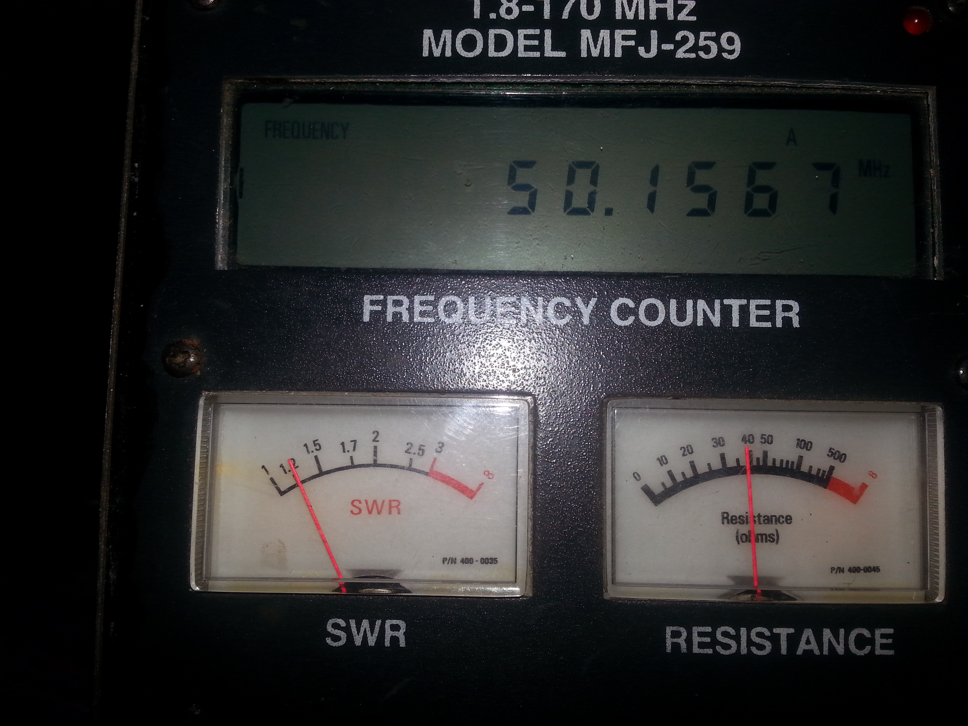
1.2:1 SWR right at 50.155 MHz.
As for the tuning: check out the display of my MFJ-259 with the antenna about 12′ in the air. I hope to break out the more serious test gear soon and calculate the gain and F/B rejection specifications very soon. I’ll post an update when I get that done. Meanwhile, I’m just waiting for my Icom 7200 to get here and I’m looking forward to next Monday night’s 6M Sideband Buzzard Net sounding better than ever!
73 from KK4ICE
Recent Comments