The Gold Hill, AL 442.175(+) KK4ICE DMR Repeater went back online a little around sunrise on Saturday, June 9th, 2018. Following replacement of the burned-out MOSFET
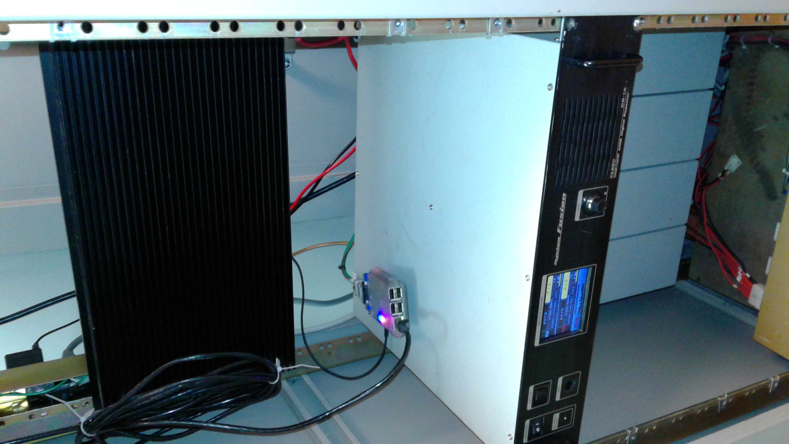
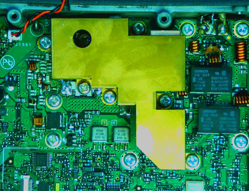
Yaesu Fusion DR-1X reinstalled at tower site, with the DMR processor/controller sitting on top. The external PA with its massive, black metal heat sink can be seen above it the repeater, and the EMR duplexers are mounted just underneath the repeater.
power amplifier chip, the repeater was reinstalled with an external power amplifier connected in order to decrease the load on (and the heat inside) the DR-1X repeater’s transmitter radio. The external PA is running at about 25 Watts and doesn’t even get noticeably warm, thanks to its having a huge heatsink attached to it. The DR-1X only has to run at about 5 Watts. The coverage and usable area for the repeater does not appear to have decreased to any noticeable degree, despite the fact that it’s running at 25 Watts of PA output (EIRP of 40.6 Watts after antenna gain and system losses), compared to it running at 44 Watts PA output (71.5 Watts EIRP) before the MOSFET melted down. Shortly after the repeater went back online, I was able to have a handheld radio to handheld radio QSO with one of our local Amateur Radio and DMR enthusiast buddies down in the Tuskegee, AL area. Not only was I delighted to see that the coverage and usable area seems to be essentially the same, but it further increased my appreciation of the DMR digital codec’s capabilities. How so? It’s because that user wasn’t able to work the repeater with a handheld from the same location when the repeater was previously running analog FM at 86 Watts (139.8 Watts EIRP.) More coverage at less than 1/3 the previous power level without any changes in antenna height or duplexers. Nice.
Soooo… I’ve managed to get a larger usable area of coverage for the repeater despite the fact that I’ve reduced EIRP of the repeater system from 139.8 Watts to 40.6 Watts by converting from analog FM to DMR digital. You gotta love that! What repeater owner wouldn’t appreciate the ability to reduce the heat and stress on his or her equipment while increasing the coverage of their repeater?
Details of the repair (MOSFET final replacement) of the DR-1X repeater’s FTM-400 transmit radio
Here are a few photos and details of the repair and replacement of the MOSFET in the DR-1X, which was quite an interesting task, to say the least.
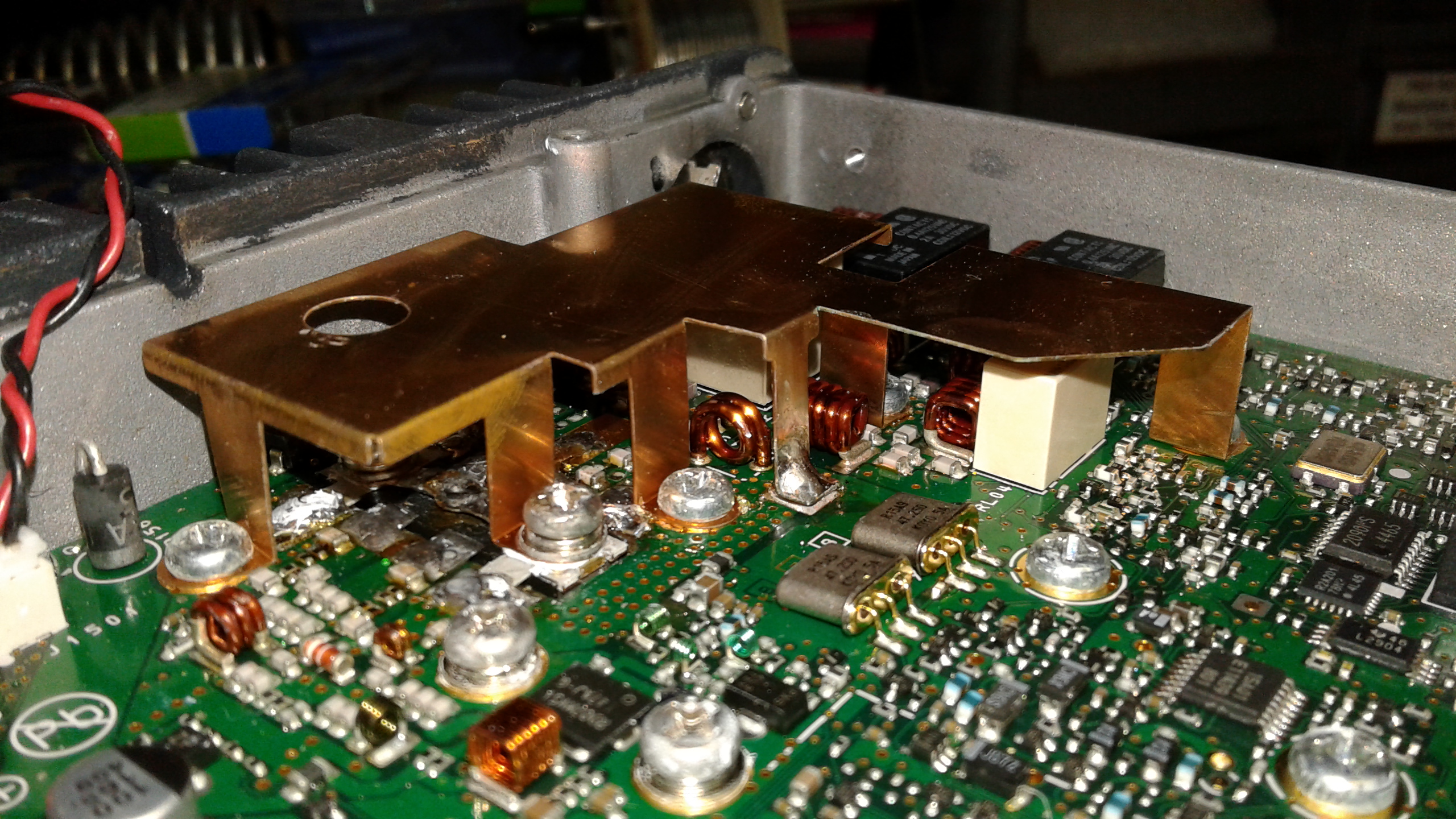
The PA MOSFET in the DR-1X transmit FTM-400 is located underneath the left-most end of this copper shield.
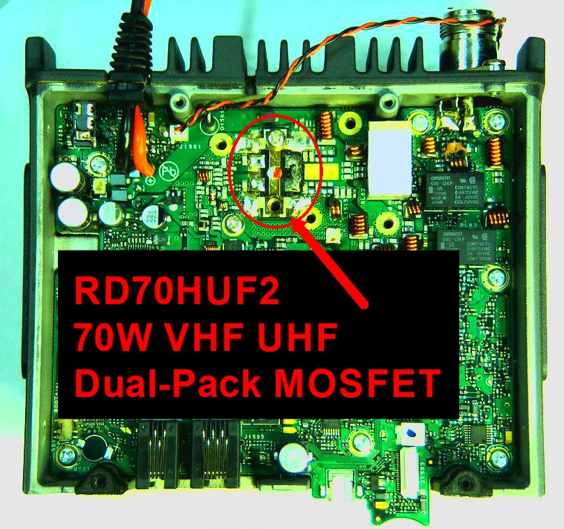
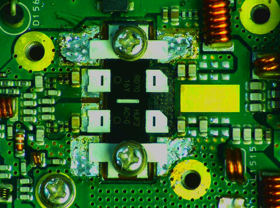
With the shield removed, the MOSFET can be seen here. This is a MOSFET, so static-precautions must be adhered to when handling and installing the replacement MOSFET in order to avoid destroying it. The current cost of this MOSFET is around $30 plus shipping.
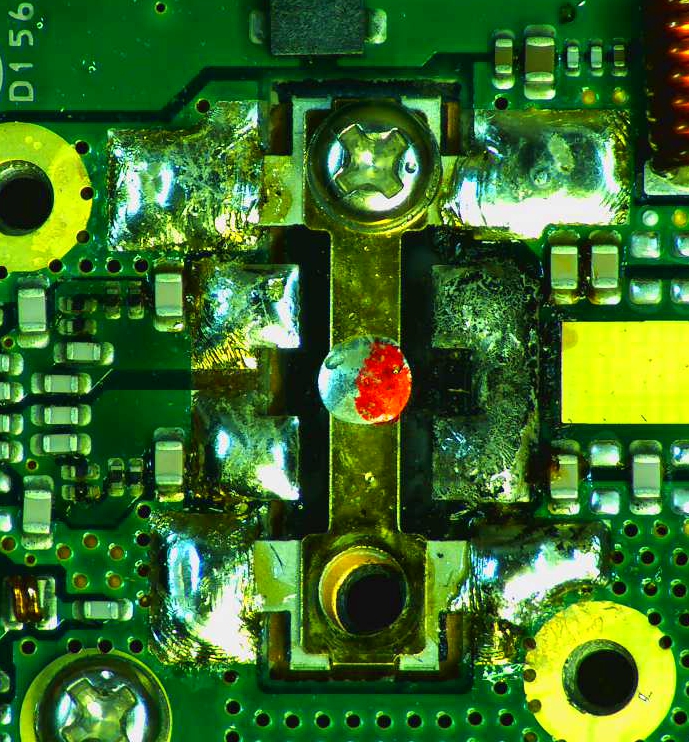
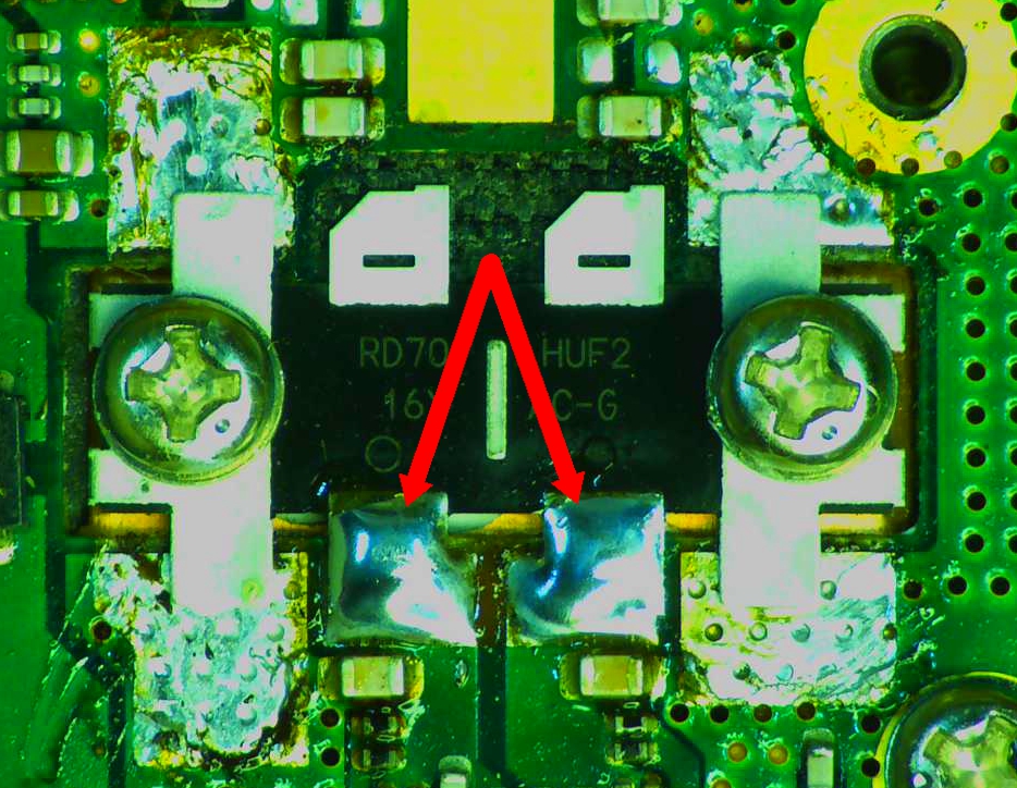
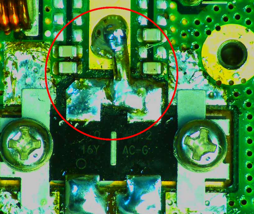
To the right of the red mark on the MOSFET, you can see where the two drains are soldered to a metal pad on the board. This is where the output of the two MOSFETs get tied together. You dark discoloration in that area is indicative of tremendous overheating in that area.This is why it’s not a good idea to run a DR-1X at full power — most especially if the duty cycle will be high. Although this MOSFET is rated for 70 Watts, there is nowhere near enough cooling engineered into the FTM-400 radio used as a transmit radio in the DR-1X to keep it from frying when running at or near 50 Watts. Bottom line: just don’t do it. I’m totally speaking from my personal experience here, and many others will attest to this being true.
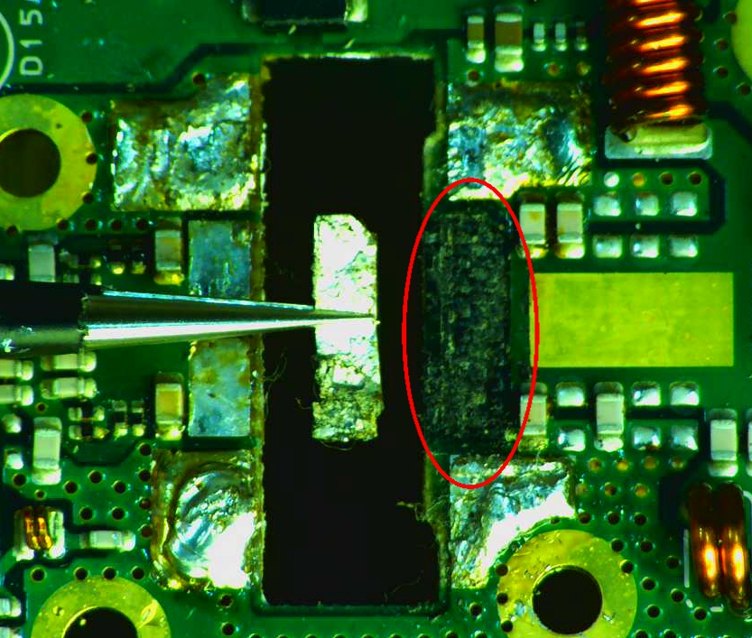
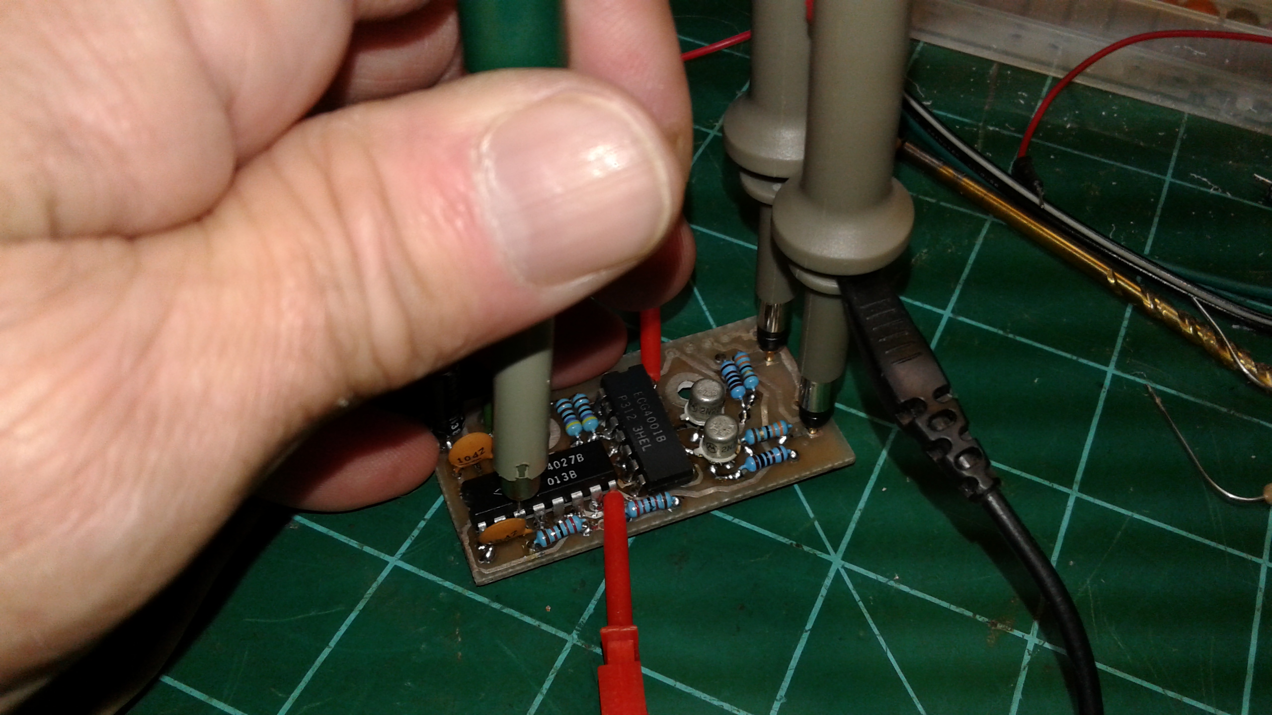
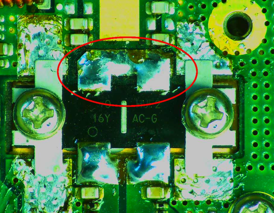
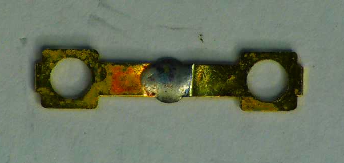
This little piece of metal I was holding with a set of tweezers WAS a piece of the circuit board. It was originally located in the area indicated by the red ellipse; however, the heat from the MOSFET got so intense that it literally burned the board underneath that metal solder landing (which was part of the circuit board.) The board was charred underneath that piece of metal.
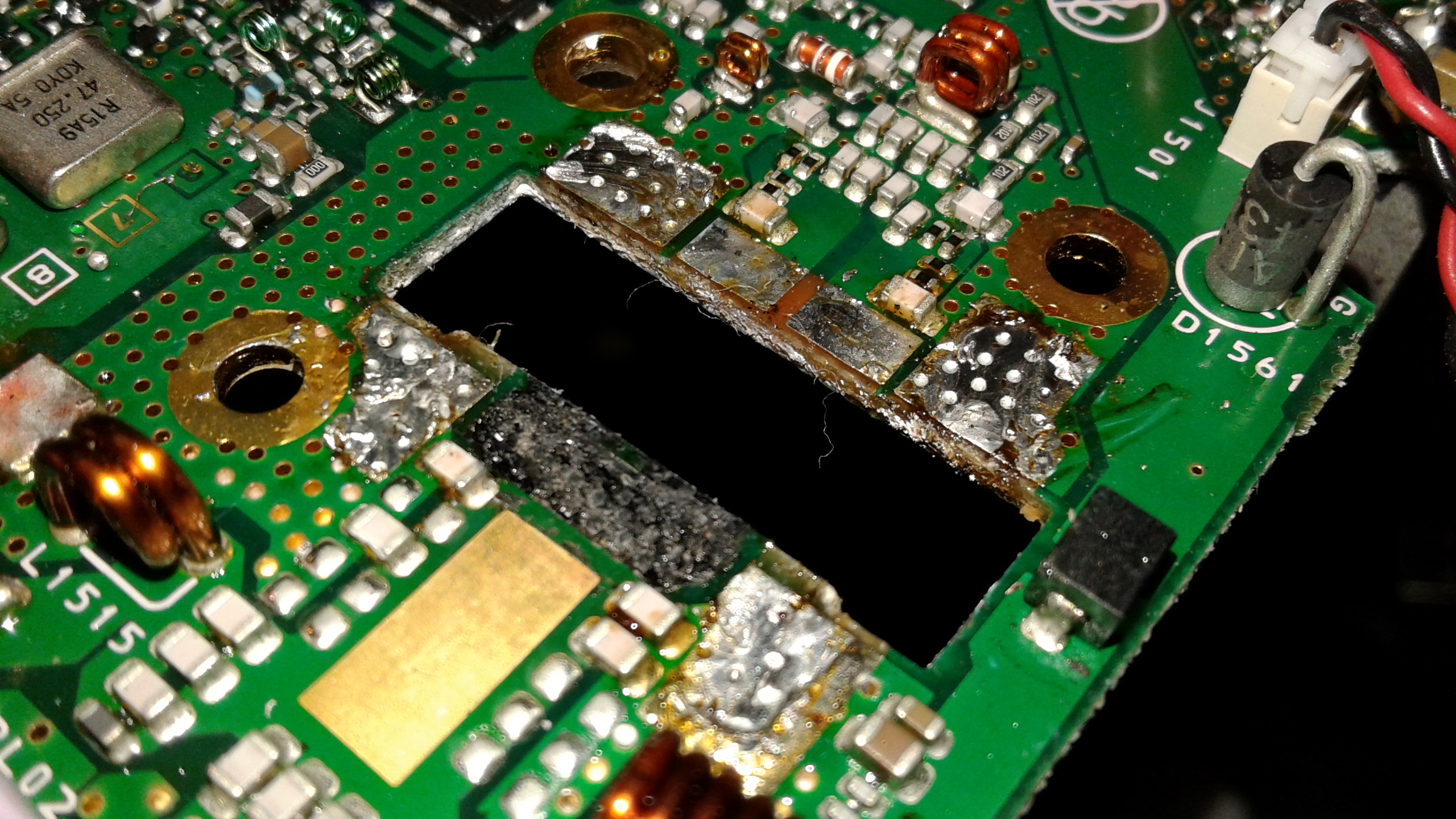
A view of the FTM-400 board with the MOSFET removed. You can see just how badly this board got heated up by the MOSFET before it finally gave up the ghost.
R.I.P., little RD70HUF2…
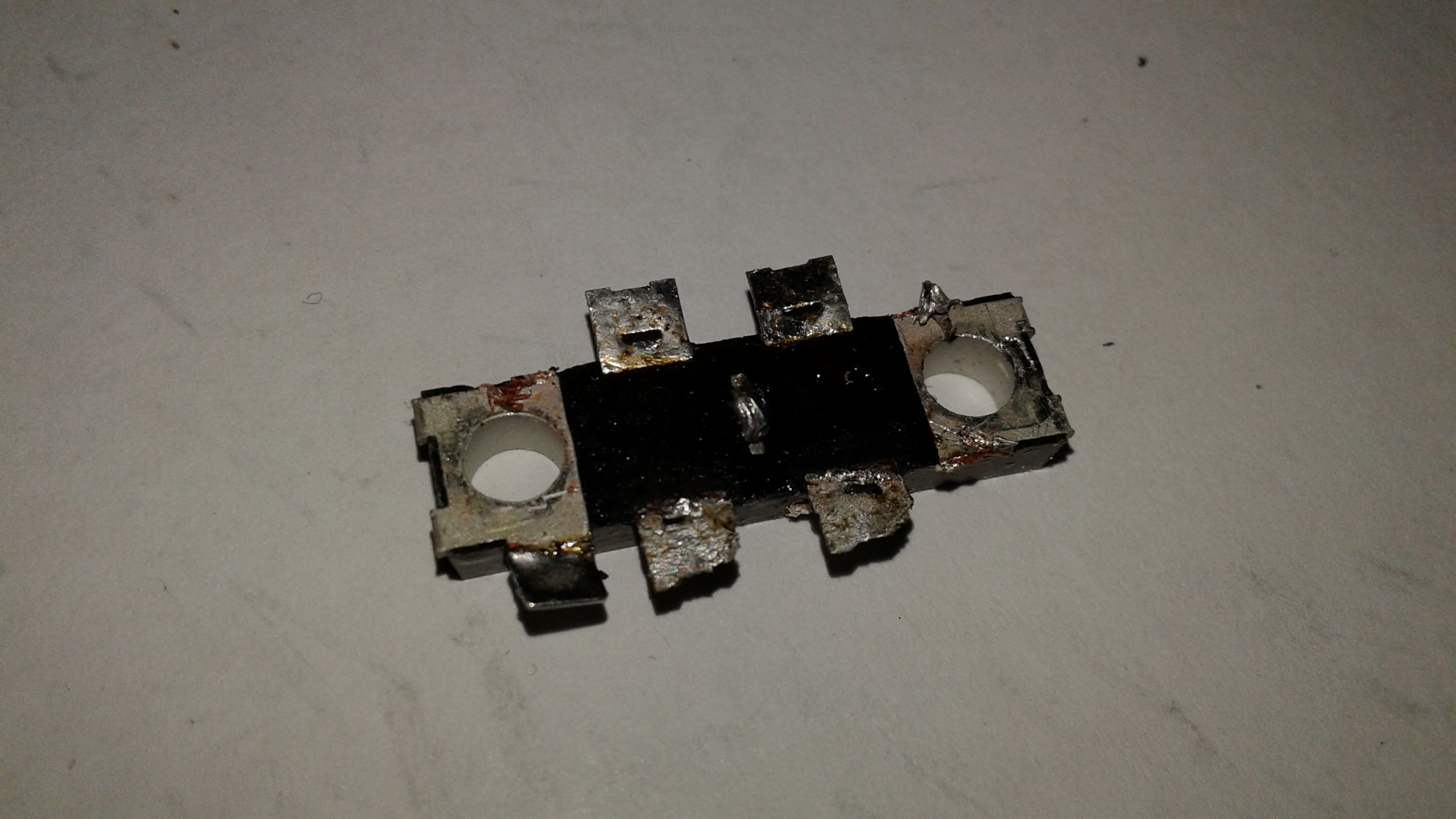
Did someone say they like their MOSFETs very well done? Yaesu will be quite happy to make that happen. Just set your DR-1X on “HI” power level and let ‘er rip.
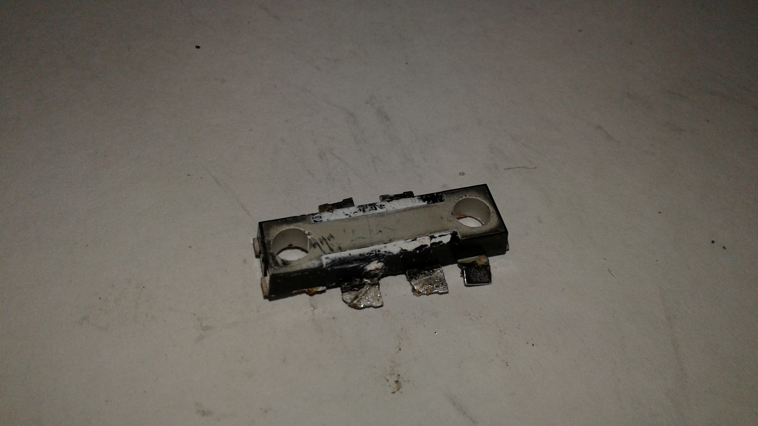
A view of the burned-out MOSFET “belly up.”
In order to make certain that the grounding screws would line up properly when the board was reinstalled, I had to temporarily place the board back inside the radio chassis and put the two screws back in. This facilitated tack-soldering a couple of tabs before taking the board and screws back out to solder the remaining tabs on the MOSFET. If you neglect to do this, much cussing will ensue shortly thereafter, because the two screws most likely will not line up properly, causing you to have to desolder the MOSFET and start over, which it most likely won’t survive due to the heat involved. It’s impossible to solder some of the tabs to the board with it in the chassis, because the chassis itself acts as a very large heat sink for some of them. Trying to solder those with the board in the chassis would do nothing but burn the MOSFET and the board to a crisp without the solder even bonding anyway.
These two tabs don’t contact the heatsink/chassis, so I soldered them to lock down the position of the MOSFET before taking the board back out of the chassis to proceed with soldering and repair. You might want to make a mental note of that very narrow little contact strip right in the middle of the MOSFET, between the two sections of the part number marking on it. This will be important later (and a major PITA, as I and many others have discovered.)
With the board back out of the chassis, my next step was to solder the piece of metal which had been burned off the board to the two drain tabs on the MOSFET, bridging them together as in the original circuit. However, this piece of metal was no longer connected to the rest of the board, so a little creative engineering of sorts was in order. The next photo shows what I had to do to resolve that matter.
I added a strip of heavy copper from the bridged drains to this exposed, gold contact area of the circuit board, to recreate the connection to that part of the FTM-400 board’s circuitry.
Remember that tiny little contact strip in the middle of the labeling on the top of the MOSFET? Well, that’s where this annoying part of the process kicks in. This piece mounts underneath the two screws AND it has to be soldered to that tiny little contact. Sounds simple enough, but trust me: you’d better have a serious soldering iron with a broad, chisel-style tip so you can get on and off the job FAST. If you apply heat in that spot for any length of time, you can go ahead and write-off the MOSFET and order yourself another one. Oh, just by the way, even with very high quality flux and solder, that tiny contact still doesn’t like to take a solder bond. It has to do with the fact that tab actually goes to a much larger conductive area inside and near the belly of the MOSFET, so it manages to dissipate the soldering iron’s heat. Such a shame the thing doesn’t seem to transfer and dissipate heat that well when the doggone radio is transmitting, huh?
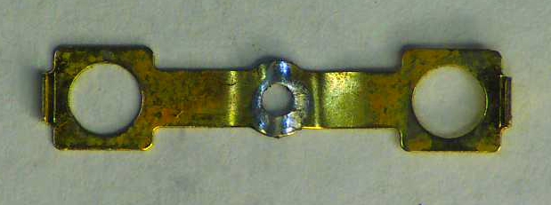
Old solder removed from the tab, shown here with the bottom side of the tab/strip turned up.
With the new MOSFET installed,the board back in the radio chassis, that little jumper clip soldered back in place (I’m still cussing that part of the job), and the shield replaced over the area, the job was complete.
A further note of caution: when the board is removed from the chassis, it’s critical to make note of everywhere heat sink compound had been used and apply new heat sink compound to those areas. Plenty of it. Lots of it. This baby produces a lot of heat and failure to put plenty of heat sink compound in the proper locations will dramatically increase the odds of failure of the RD70HUF2 dual-pack MOSFET.
Post-operative note from this “radio doctor,” as some have referred to me: if I were to perform this surgery/repair for someone else, it would be about a $200 job (MOSFET included.) This is definitely NOT your run-of-the-mill parts swap-out. It would be very easy to destroy the replacement MOSFET in the process of installing it. This job is not recommended for anyone who is not very confident in their soldering skills or who is not equipped with high quality soldering equipment. Then again, I’m sure there’s someone at RF Parts Company who’d like to retire some day…
I hope hams in our area get great enjoyment out of the DMR repeater being back on the air. I sure am. We’re on the East Central AL DMR Talkgroup, Brandmeister TG number 310023. Come on and join us!
73 everyone,
KK4ICE
Recent Comments