Last Friday, we pulled KE4COL’s Mastr II 2-Meter repeater out of service due to some intermittent “crashes” on COS drops, strange noises, etc. which had been occurring for a while. I brought it here to the lab and finally got around to going through it today. I found and addressed a few issues and it seems to be behaving better now.
Problem #1: 10-Volt regulator card adjusted too high.
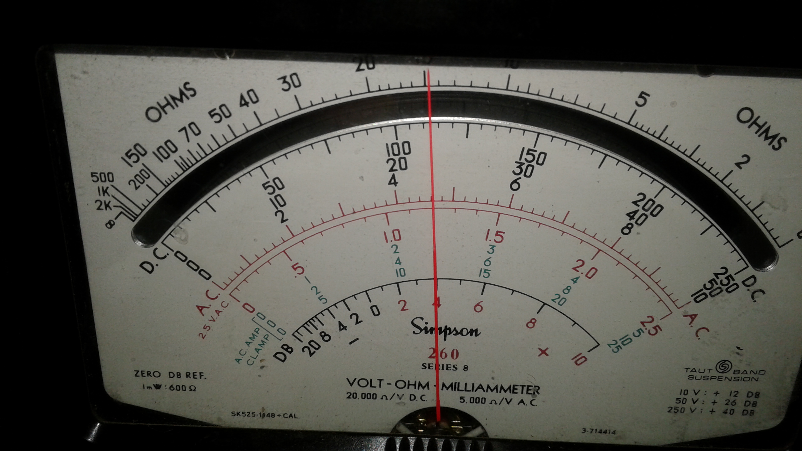
Fig. 1: 10-Volt Regulator Card output voltage was around 11.25 VDC prior to adjustment. Meter was set to 25 VDC scale.
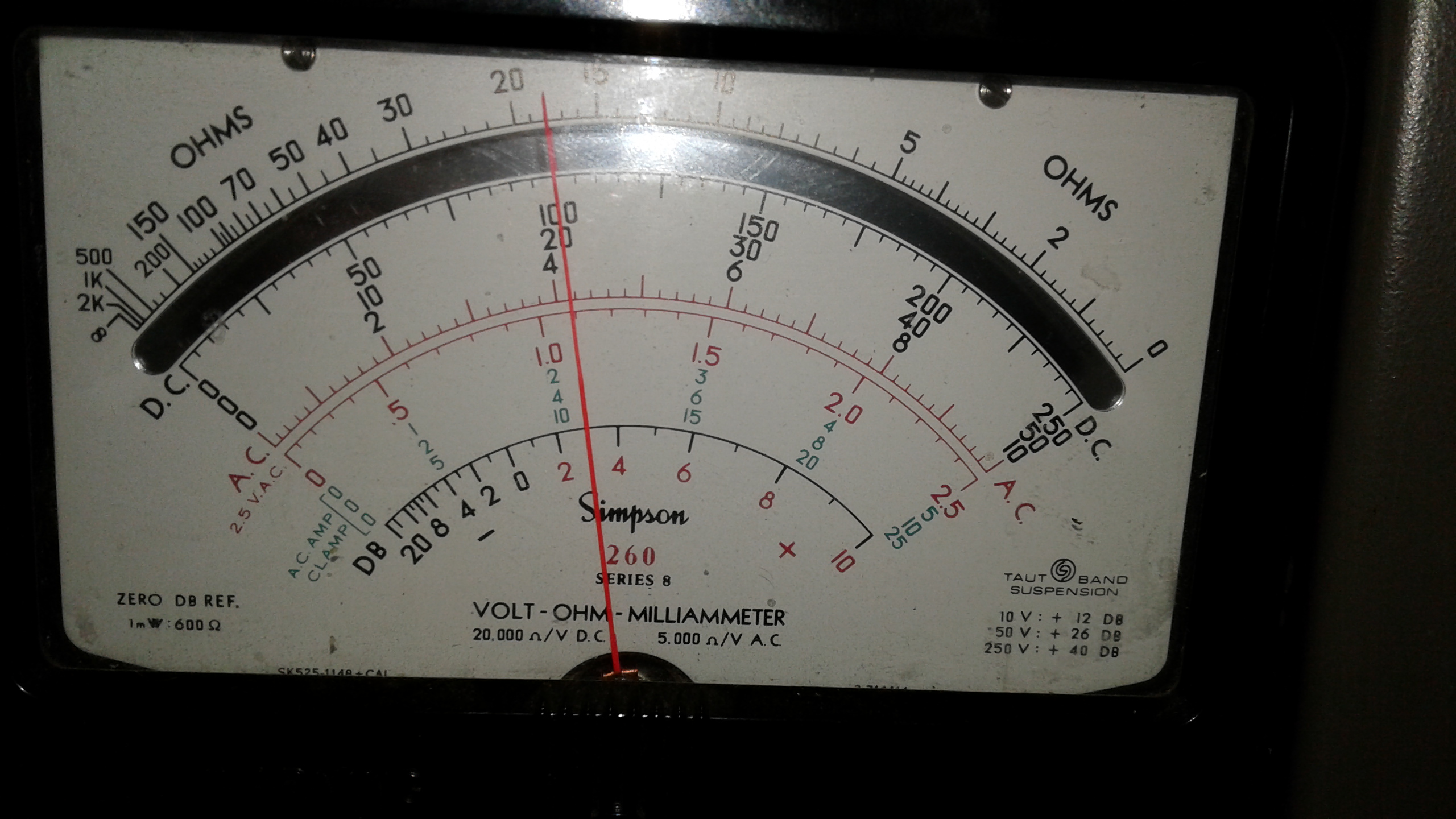
Fig. 2: DC Voltage after adjustment to 10 VDC, as seen on 25 VDC meter scale.
As can be seen in these photos, the 10V regulator card was set a bit too high and was putting out around 11.25 volts. I adjusted that back to the proper 10 VDC and it holds rock solid whether idle, receiving only, or transmitting. This voltage is critical, as the temperature compensation circuits for the crystal elements depend on having the correct voltage to begin with.
Problem #2: Tx Frequency a bit farther off than I like to see.
I try to keep the transmit channel elements as close to the desired output frequency as possible. The machine was transmitting 126 Hz above the desired 145.230 MHz output frequency, which isn’t a
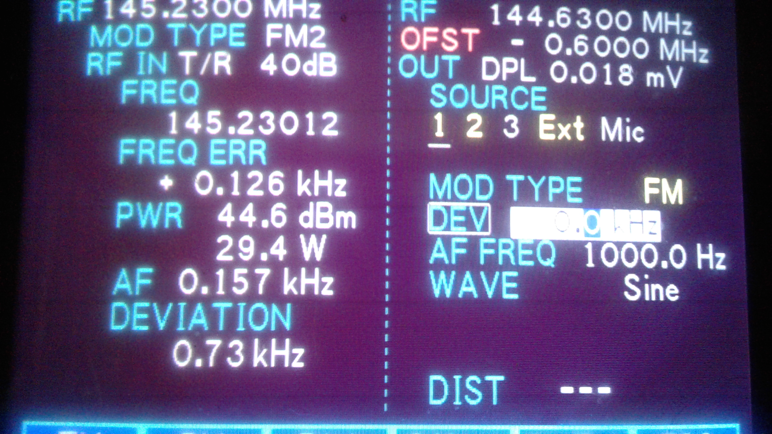
Fig. 3: Transmitter frequency was +126 Hz from desired frequency prior to re-netting the crystal.
tremendous error (and is within FCC tolerance); however, it isn’t as close as I like for the frequency to be, especially since I do my tests using calibrated instruments running on a 10 MHz GPS Disciplined Oscillator reference standard.
As can be seen in figure 4, I re-netted the crystal to within +1.0 Hz during my testing and alignment of the machine. I can see it fluctuate between about -4 Hz and +8 Hz, which is normal, and well within tolerance.
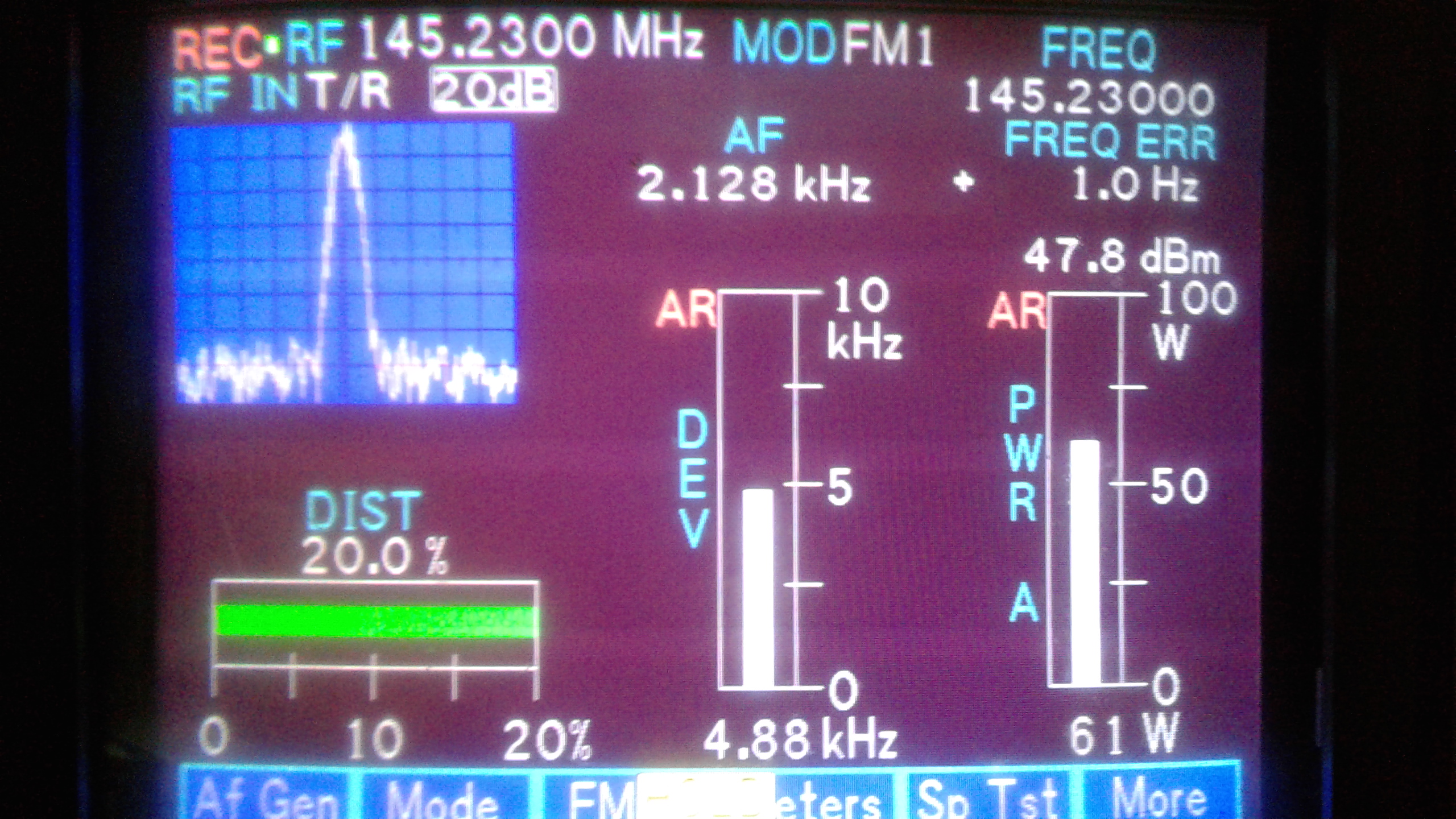
Fig. 4: Exciter and Power Amplifier performance after troubleshooting, addressing a few things, realignment, and final adjustments.
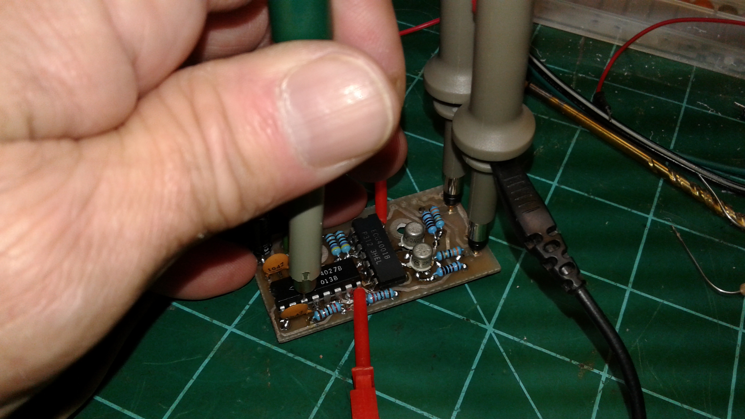
Problem #3: Possible noises being generated by running P.A. at too low an output level.
Mastr II Power Amplifiers have a reputation for acting strangely (and occasionally burning up) if they are set at relatively low power levels (as compared to their “rated” output wattage.) As can be seen up in figure 3, the amplifier had been adjusted down to 29.4 Watts recently. That had been done because the repeater seemed to have a desense issue. At that time the duplexers were brought to the lab and it was found that five out of the six cavities had mysteriously gotten misaligned after the last tuning and testing was done on them. When the duplexer was put back in service, the power output level of the P.A. was not re-adjusted.
The situation today was that I did manage to get some strange noises out of the machine occasionally (along with higher than usual background static/white noise) in the transmitted signal as heard on the IFR-1600 service monitor. When I adjusted the power up to 60 Watts, that seemed to clear up, leading me to suspect that the particular P.A. on this repeater is one of those which doesn’t play nicely below about half of its rated power (this is a 100 Watt P.A.)
Potential Problem #4: Dirty and/or loose RF and terminal connectors.
Let’s face it: these babies haven’t been built in decades. Many (most?) of them are starting to show more and more signs of aging. This includes natural oxidation and fitting issues with RF connector cables, multi-terminal connectors, and other connection points. Before going through all the final re-alignment and testing stages, I pulled, inspected, and reseated every cable, card, and connector which is removable. I gave all of the RF connector cables a thorough wiping with alcohol and Q-tips. before reseating them. All of the cards/boards up in the card cage were also pulled and the contacts given similar alcohol and swab treatment before being reseated.
Problem #5: Modulation level was a bit low.
With a 1 KHz tone test signal at 3.5 KHz of modulation hitting the receiver, it was transmitting with a modulation level of around 3.4 KHz. I like to keep the modulation level on a Mastr II adjusted so that 3.5 KHz deviation on a received signal will produce around 4.5 KHz of modulation of the transmit signal, and I set the “cap” on the modulation such that a way overdriven incoming signal (I use around 7 KHz incoming as a reference) will not cause the output of the repeater to exceed 5.0 KHz. In figure 4, I was hitting it really hard and the modulation topped out at 4.88 KHz.
Prognosis and game plan
My plan is to leave the machine running here in the lab for a few days, keying it up witih the communications analyzer and a variety of H/T’s for a few days. While it’s running here, I’ll give it the occasional “bang and knock” tests — literally, I will occasionally bang on the equipment rack, the repeater chassis, open it up and tap and knock on the frame, boards, etc., in order to determine whether any potential contact issues surface or resurface. There are few things in the world more annoying to electronic and communications technicians than pesky intermittent problems which only manifest themselves when you have your back turned (actually, more like when you’re miles and miles away from the repeater site.)
Hopefully everything will continue to check out well and we’ll get the repeater back up to the site and online again by the weekend. Keep your fingers crossed, everyone. There’s not a technician I know of (myself — especially — included) who will turn down some good luck to go along with any amount of skill and experience. On the other hand, if this machine continues to give us intermittent issues on a regular basis, we might resort to plan “B”, which would involve starting with another complete Mastr II and building a replacement for this one.
73 and stay tuned for updates,
KK4ICE
Recent Comments