I happened to mention to a fellow ham that I’d been wanting to convert a toaster oven into a surface mount technology reflow solder oven. As it turned out, he’d had the same
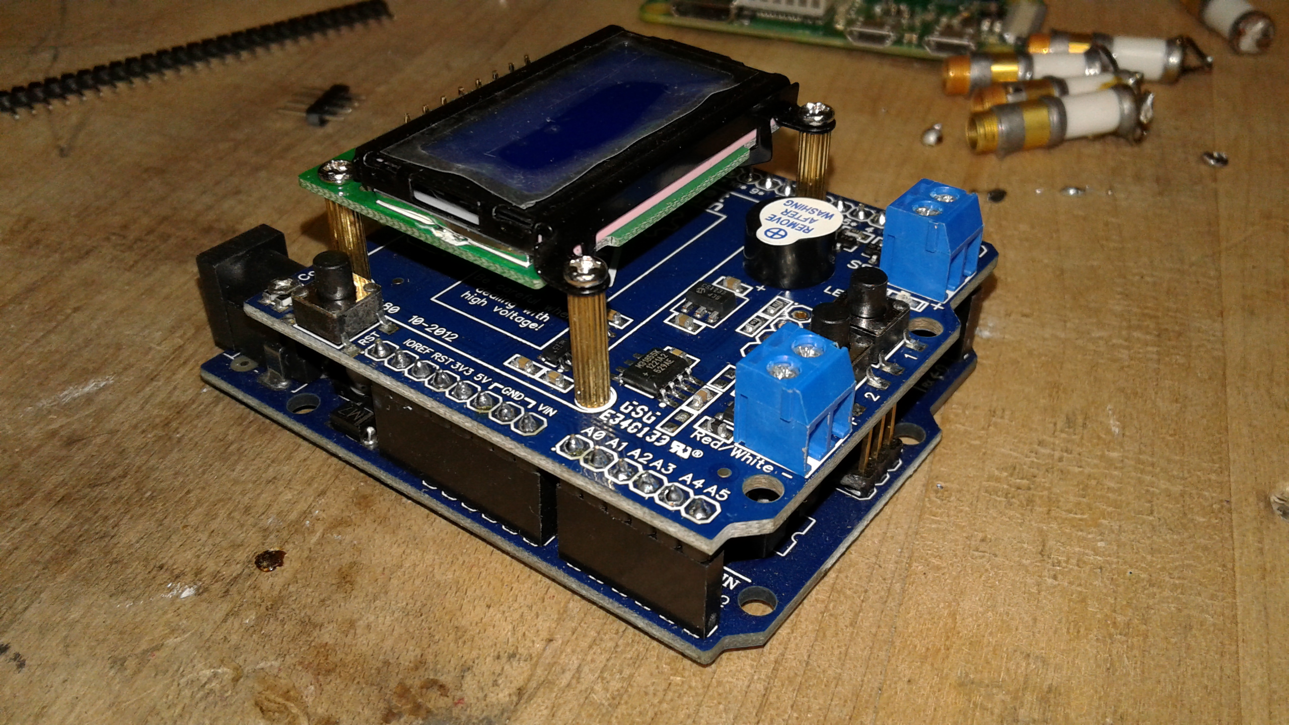
The Surface Mount Solder Reflow Oven — the final, functional version.
idea a while back, purchased a few items to start the project, but never got around to doing so. He knew I already design and make my own prototype and special projects schematics and actually make the prototype boards right here in the lab, so he decided to gift me with the reflow shield (to fit an Arduino) and the thermal probe which he had lying around unused. That started an interesting adventure which has turned out rather successfully — after a hiccup or two, and two trips to the local Goodwill store to purchase a total of three cheap toaster ovens ($20.57 tax included for all three.) More about why I had to make two trips and purchase more than one toaster oven in a bit.
Rocket Scream Reflow Oven Shield
The reflow oven is controlled by a combination of an Arduino Uno and this Reflow Oven
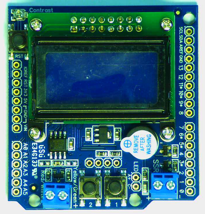
Rocket Scream DEC-00039 version Reflow Oven Shield for Arduino.
Shield from Rocket Scream. I’m not sure if this particular version shield is available from them now — they’ve come out with a slightly newer model. Nonetheless, this one wound up working just fine.
The Arduino IDE sketch to run it is readily available on the web, along with the Arduino libraries needed to support the PID and the K-Type thermal probe. Links for all of that can be found on the Rocket Shield website, and also by just a little “Googling” around.
The shield has two momentary contact buttons (although button 1 — the leftmost of the two — has no function at this time. There are contacts/solder points right above the two buttons to facilitate wiring to external buttons if you wish to install this thing inside the oven or a fancy case of some sort and put a more accessible (and larger) momentary contact switch in a more convenient location.
Adding Header Contacts To the Shield
For some reason (probably to save a nickel or so), Rocket Shield chose not to install the needed header pins on the shield which are needed to connect/piggyback it on the
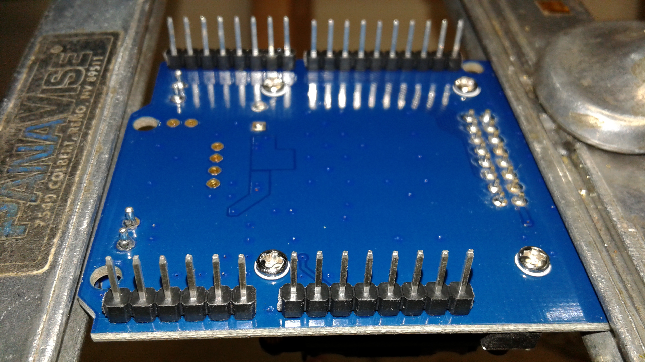
Bottom view of Rocket Scream Reflow Shield after installing male header pins.
Arduino Uno. Perhaps they figured some folks might install ribbon cables or something — who knows. No biggie, as I keep tons of header connectors in my parts inventory because I use lots of them.
With the header pins installed, it fit quite nicely on the Arduino Uno R3 board, with the expected snug, secure contact those of us who play around in the Arduino
Rocket Scream Reflow Shield attached to the Arduino R3.
world have come to expect (i.e., when you want to separate the shield from the Arduino, it takes enough force that you almost wonder whether or not you’re about to break something.)
The little shield board is actually pretty a nice, clean compact design. I’m not sure whether or not the 8×2 LCD display was included on the shield when my friend purchased it, and neither is he. Nonetheless, that’s what serves as the visual indication of what’s going on in the reflow process, along with an LED or two included on the shield and the Arduino. You also have the ability to track the oven temperature and reflow stage using the Serial Monitor function of the Arduino IDE software, if desired.
Toaster Oven #1 — Which Did Not Work Properly
A stop at the local Goodwill store netted me a Sunbeam toaster oven for only $4.94 plus sales tax. They might have priced it a bit higher if they’d taken time to clean it up a little
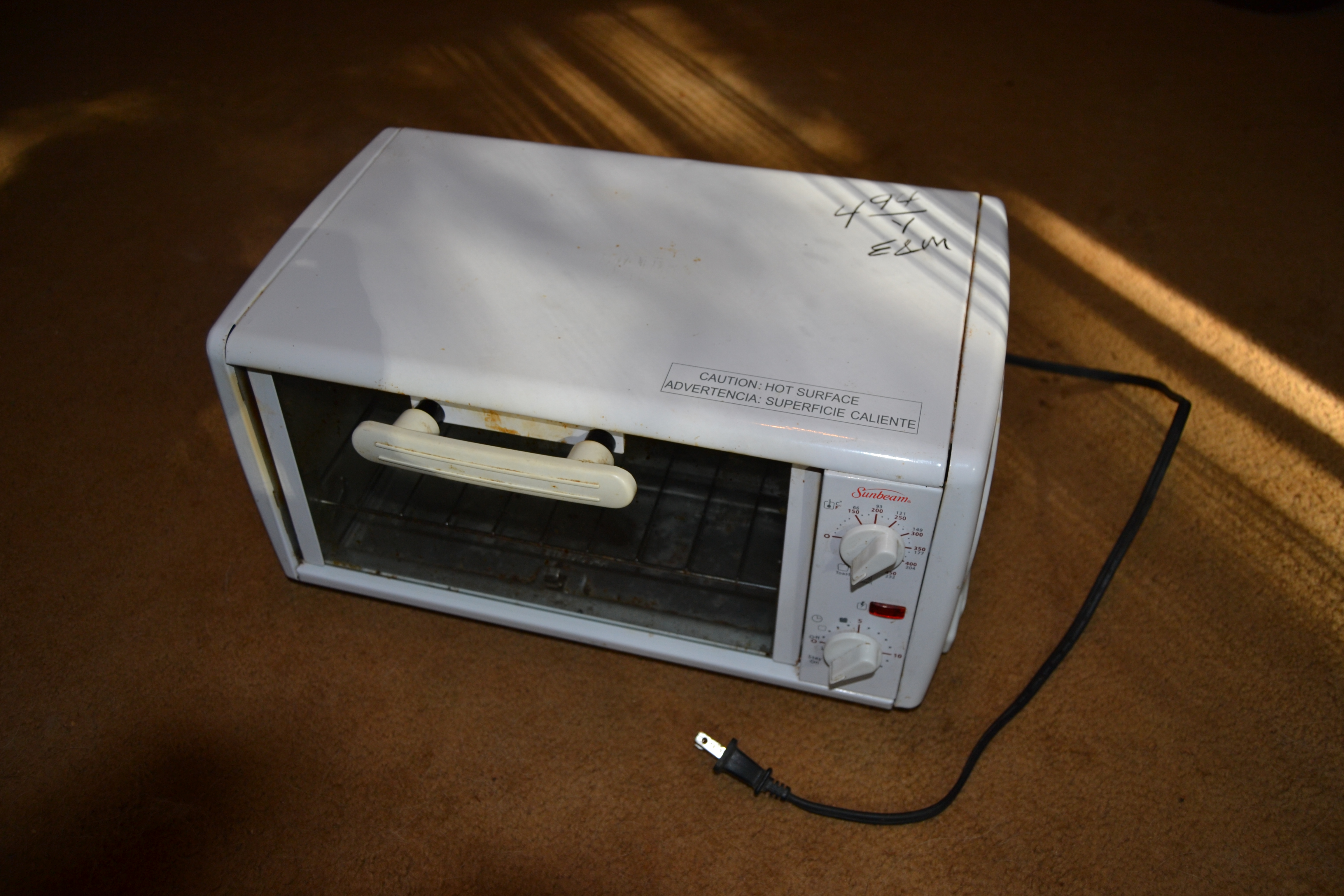
The not-so-hot (literally) Sunbeam 1350 Watt oven which turned out to be a dud. I didn’t even bother taking it back to the Goodwill store — let them keep the $5 or so as a donation to a worthy cause.
better. It was a 1350 Watt model with a relatively small oven chamber, which is actually preferable for the job because it means that it can heat up faster. Except… they don’t heat up quite so well when one of the elements is failing.
For conversion to a reflow oven, the toaster oven needs to have the radiant, quartz glass-looking type elements, which heat up and cool down much faster than the old grey, resistive, metallic type (similar to what you see in most old ovens.) This oven had the typical configuration of one heating element mounted near the top of the cooking chamber, and near the bottom. The one at the top
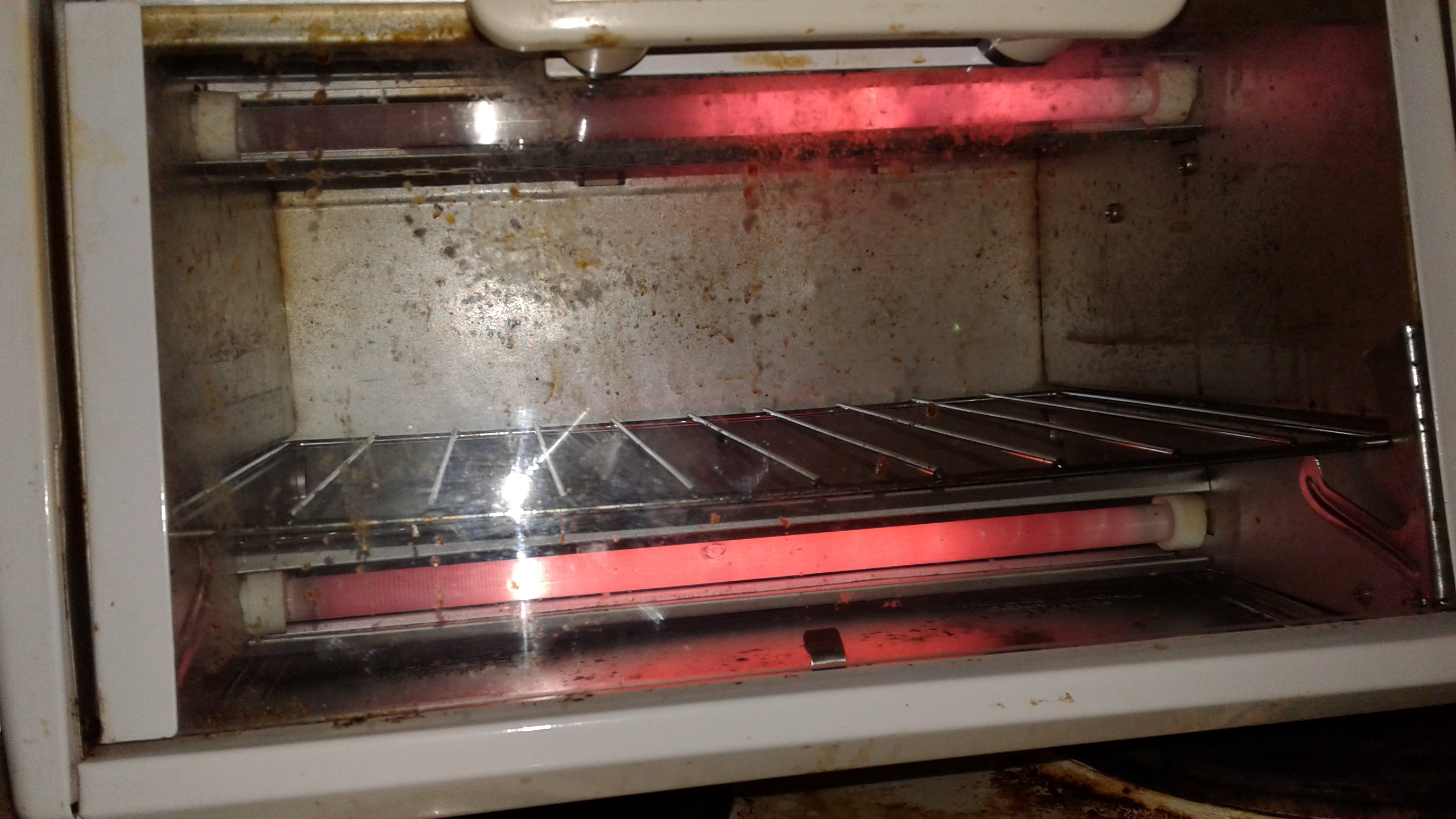
Oopsie. I guess this would be a great toaster oven for couples where one person likes their toast slightly less brown than the other?
had an obvious problem and was only heating at one end, as you can see in the photo. The chamber was also poorly (i.e., “cheaply”) designed and you could actually see daylight through the openings where the sheet metal only “almost” met at some of the corners, etc. In a nutshell, this must have been a mislabeled model. They should have instead called this the “Sunbeam POS” model. ‘Nuff said.
Another Stop At Goodwill For A Hopefully Better Toaster Oven Paid Off
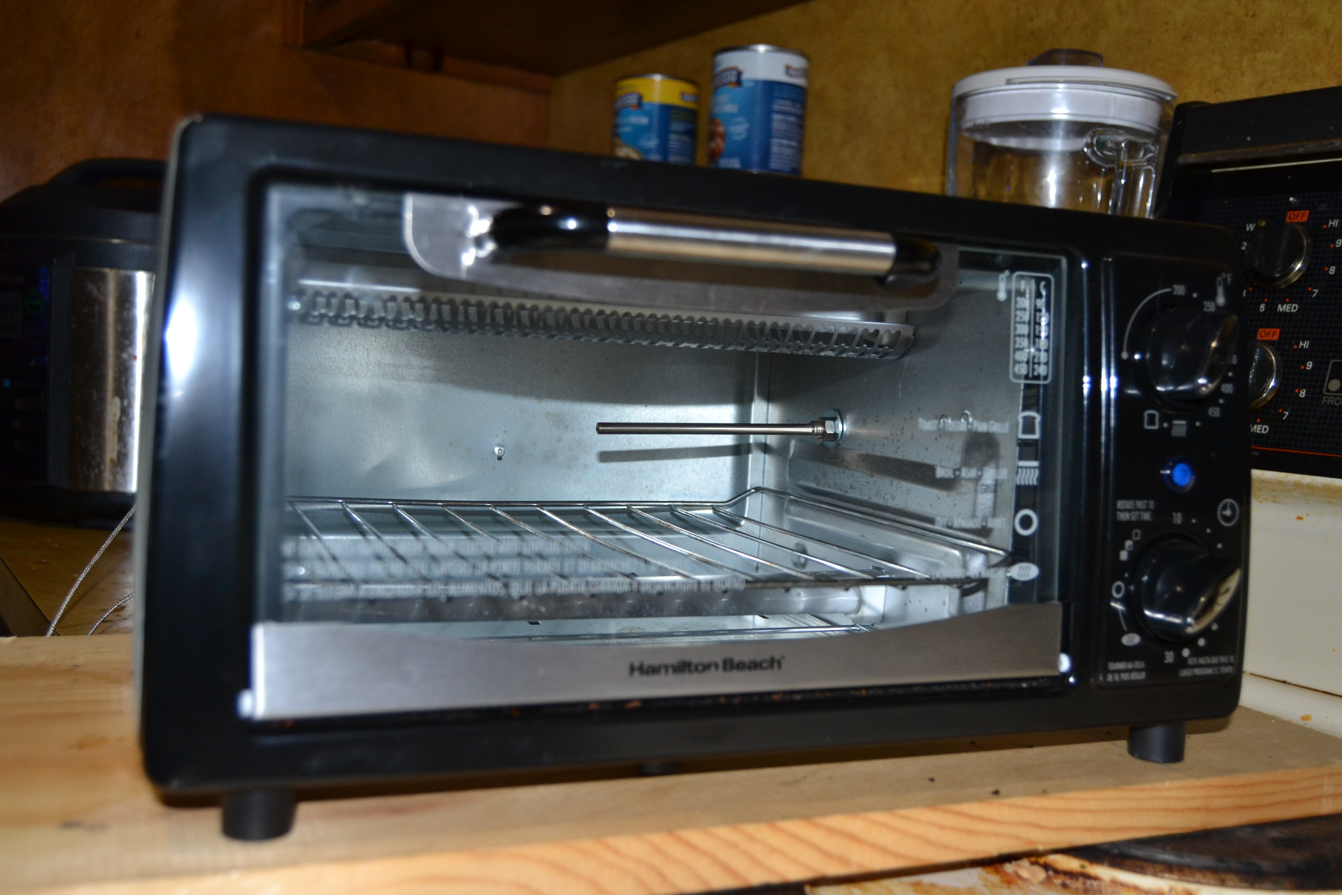
While out running a few errands, I stopped back in at Goodwill and grabbed two other prospects for a better toaster oven for the job. One was this Hamilton Beach priced at

The Hamilton Beach toaster oven. A little gem. Seen here after I’d already removed the housing and installed the K-Type thermal probe.
$9.99, and the other was a Rival priced at $3.93. The Hamilton Beach was fairly clean and turned out to work quite well. The stainless steel shell looks a bit nicer and the cooking chamber is much better sealed, without the sort of leaky areas to lose heat which the Sunbeam was riddled with. I haven’t even touched the Rival since I brought it in — one, because I wound up not needing it, and two, because I think the $3.93 price tag amounted to paying about $1.00 per pound of grease that was still on and inside the thing. N-A-S-T-Y. I still like Goodwill, although I often wonder what their criterion is for “Clean it up a bit” or “Nah, just throw it on the shelf and hope it sells” decisions.
Wattage Ratings Are Not Always That Informative
A lot of folks who have already traveled the toaster oven to reflow oven conversion road really stomp hard on the “Look for at least 1350 Watts” soapbox. I can now tell you from
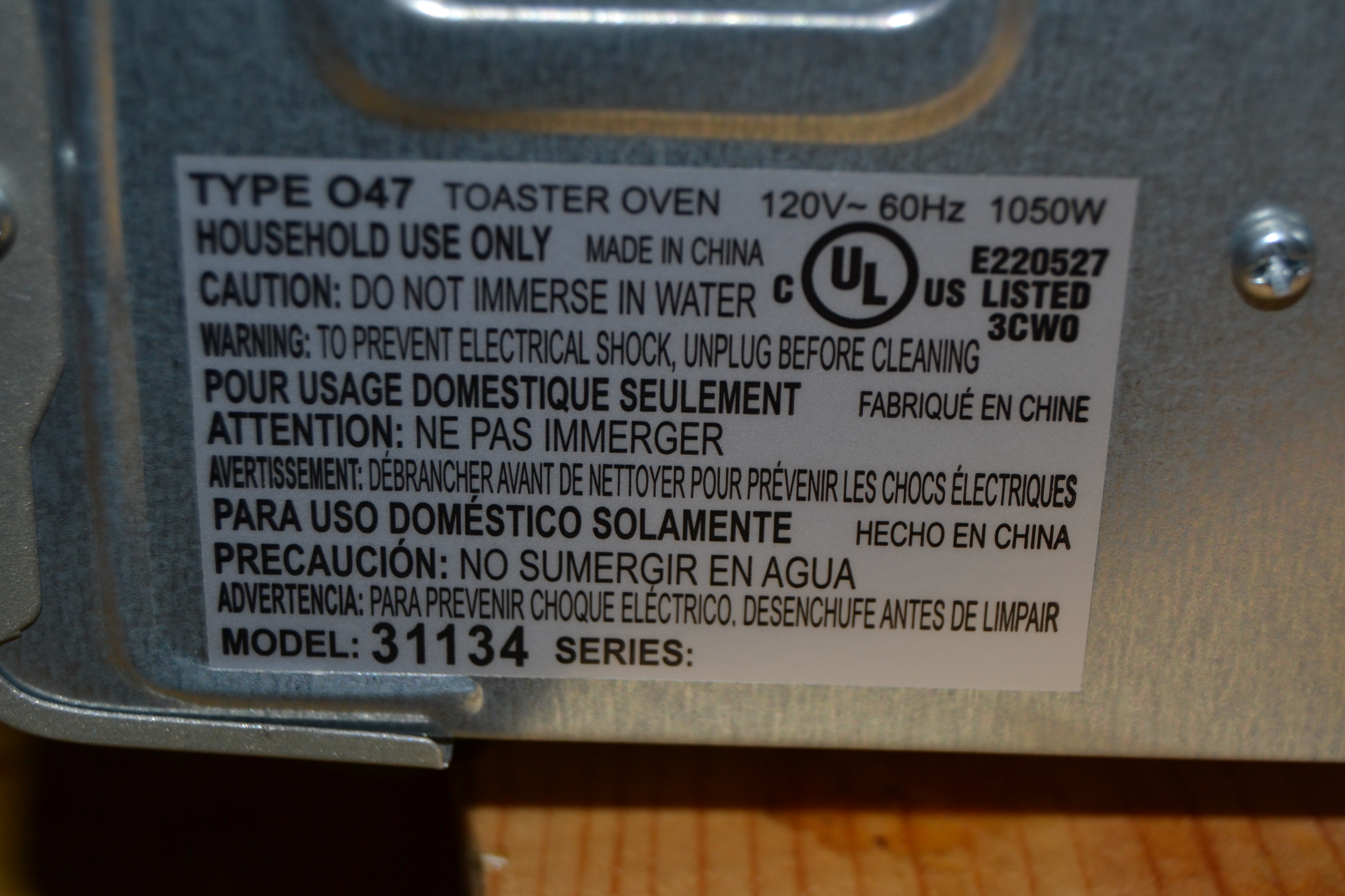
What’s in a Watt? 1050 Watts turned out to do the job as nicely as I’ve seen the 1350 and 1500 Watt ovens perform.
experience that there’s more to the suitability of a particular toaster oven for this purpose than just the number of Watts on the data label. This jewel is only rated at 1050 Watts; however, the better sealed metal cooking chamber makes up for some of the difference. Also, some of the DIY-guys who’ve done similar conversions tout the notion of purchasing a welder’s blanket from Harbor Freight to use as insulation to wrap around the outside of the metal cooking chamber (which I *almost* did, until I saw the $24 price tag for the smallest one and decided to hold off on that unless testing revealed it would be significantly helpful, which it didn’t.)
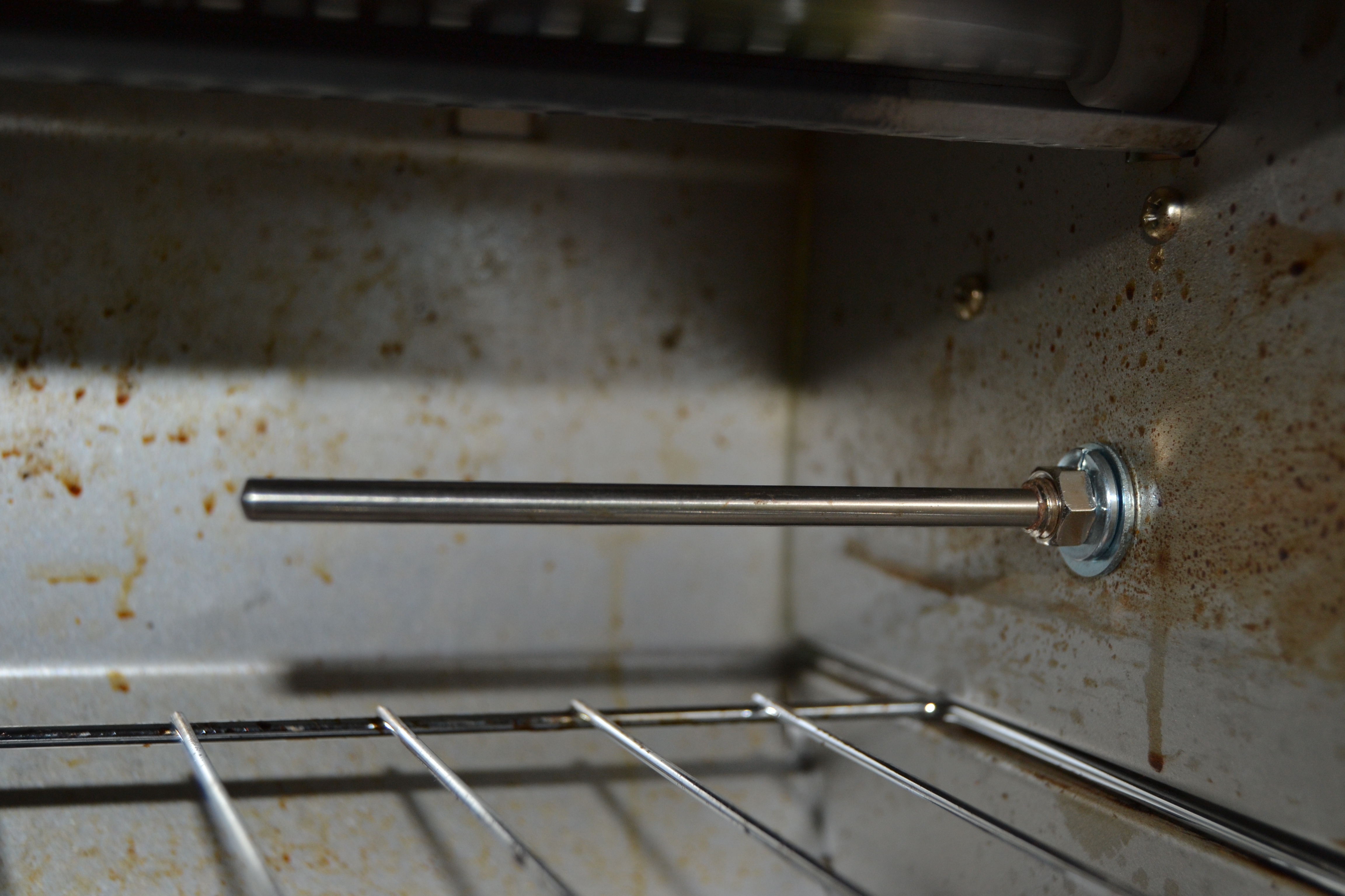
Thermal probe mounted — interior view.
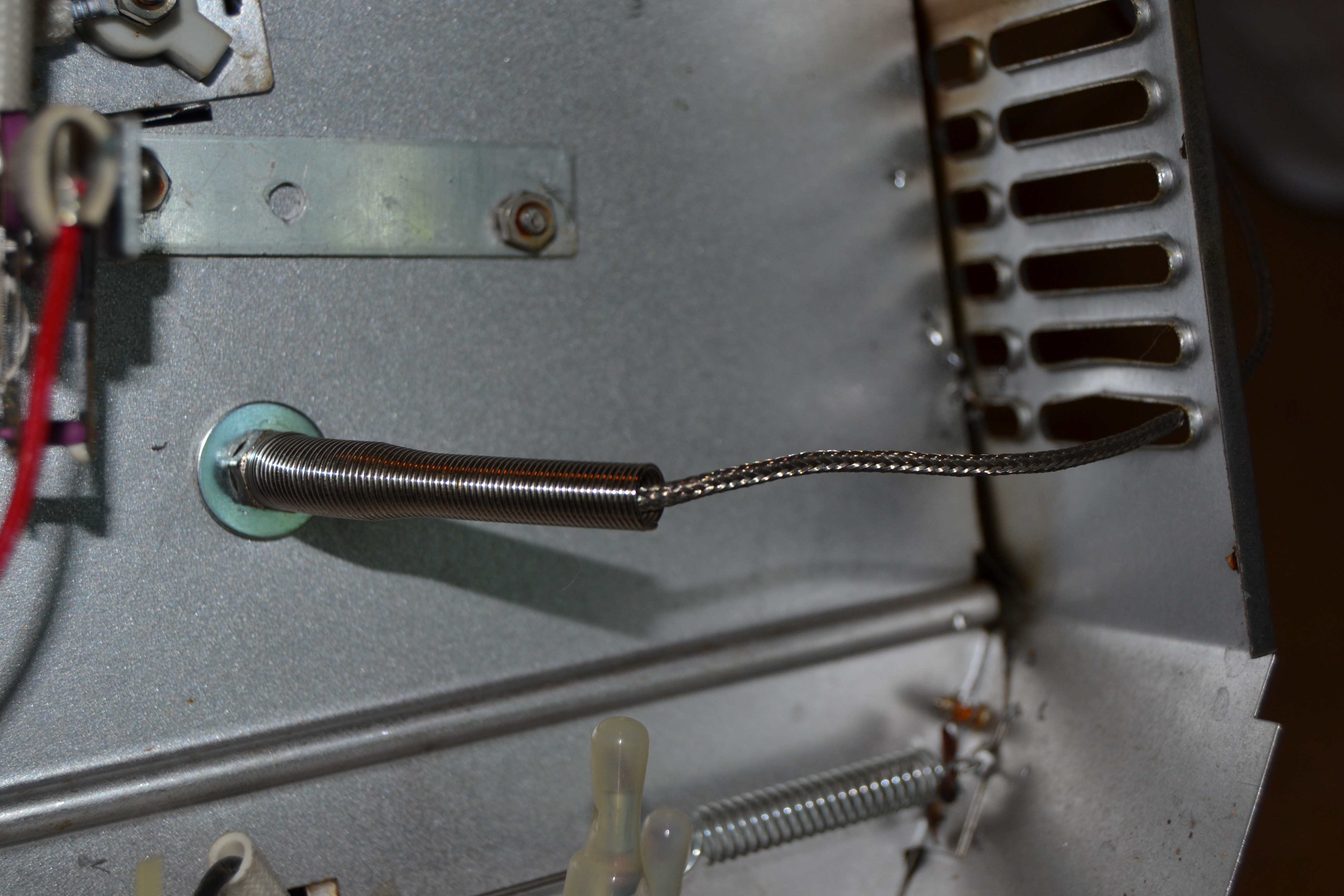
Thermal probe mounting — view from outside the cooking chamber.
Shown here is how I mounted the K-Type thermal probe in the oven. Although the photos of the installation are actually from the first oven, I installed it exactly the same way in the second oven. I just drilled hold through the side of the cooking chamber so that the probe would end up positioned fairly close to where the board(s) would be during a reflow run without actually getting in the way of the boards. I simply routed the teflon shielded probe cable through on the case vent slots at the back of the oven on the control panel end. Done tater.
Because of the fact that the wire spring and teflon coating of the thermal probe cable is in the vicinity of the “hot” AC wiring end of the heating elements, I didn’t want it to be able to just flop around in there or for the wire/spring to inadvertently get pushed partially back through the vent and end up touching 120 Volts of AC, a little foil HVAC tape was used to secure a section of the cable to the back of the oven case.
Solid State Relay for Controlling the Heating Element AC Power With the Reflow Shield and Arduino Combination
So, we (Arduino enthusiasts) all know that you can’t just switch 120 VAC with the contacts on an Arduino. The Rocket Scream Reflow Shield can’t do that either. But what it does do is provide a small DC voltage (roughly 5 VDC at about 5 mA) to drive a solid state relay which, in turn, can control/switch 120 VAC or more at a much higher
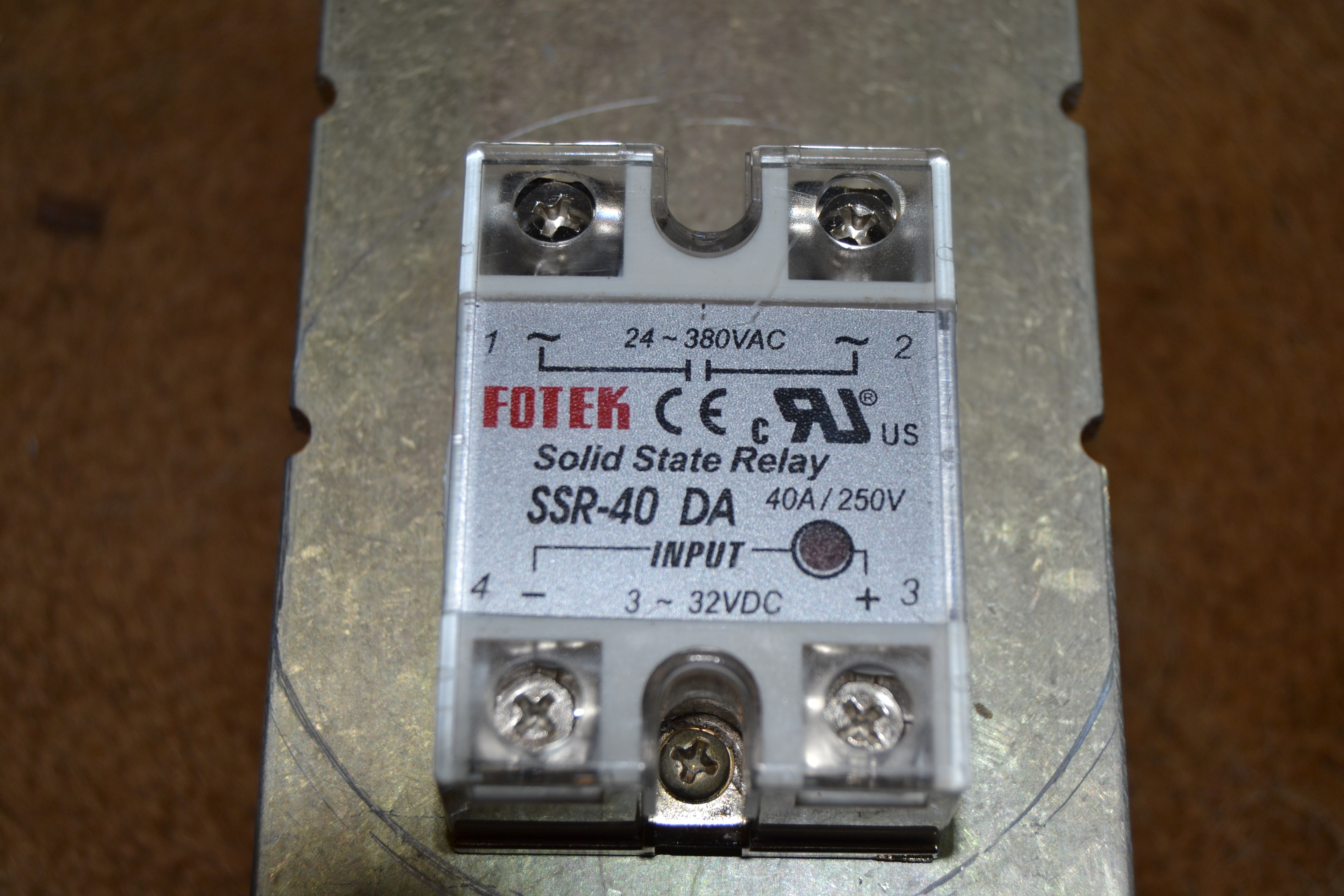
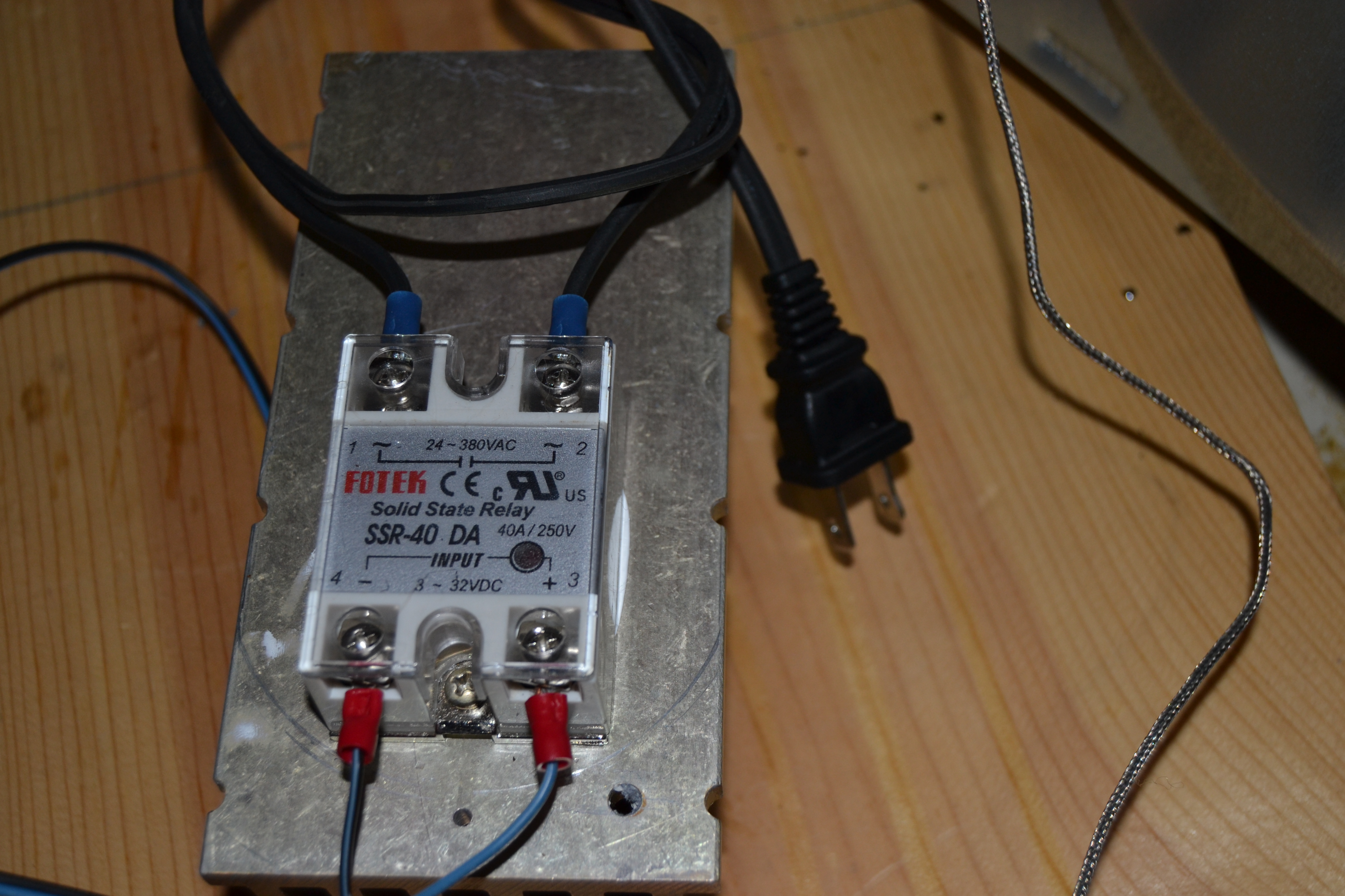
40 Amp SSR (Solid State Relay.)
amperage/power rating. In this conversion, my buddy had purchased and passed along a relay which can handle up to 230 VAC and is rated for up to a whopping 40 Amps. Talk about playing it safe! LOL. Let it never be said my buddy likes to cut corners on power and safety.
A solid state relay (SSR) under high current handling conditions can get pretty warm. So I decided to do the recommended thing and mount the SSR on a heatsink, external to the oven, and hopefully use a large enough heatsink that no cooling fan
would be required for it. I knew there was a reason I salvaged those heavy, brass-looking (actually aluminum alloy) heatsink sections off the back of some G.E. Mastr II power amplifiers before discarding the guts of the things. One of those turned out to be perfectly suited for the job.
After cleaning all the old thermal/heat sink compound off the heatsink, I used a ruler and Sharpie to draw a line along the mounting side of it so that it ran parallel and in between
a couple of the cooling fins. I then marked the locations for holes to line up with the mounting screw holes on the SSR were located. It was pretty obvious that getting between the fins with any sort of tool for attaching a nut to a small bolt was not going to work. Fortunately aluminum is pretty is to tap threads into with a tap-and-die set. Digging through assorted hardware on-hand, I determined that a couple of 6×32 bolts would work well. According to a popular site, the proper hole size to drill for tapping for a 6×32 bolt is 7/64″. Simple enough. I had a 7/64″ drill bit, so I just ran to the drill press and had that done in just a couple of minutes. Then I proceeded to tap the holes to 6×32. THAT didn’t go as planned. Next lesson learned in this job (well, relearned, as I
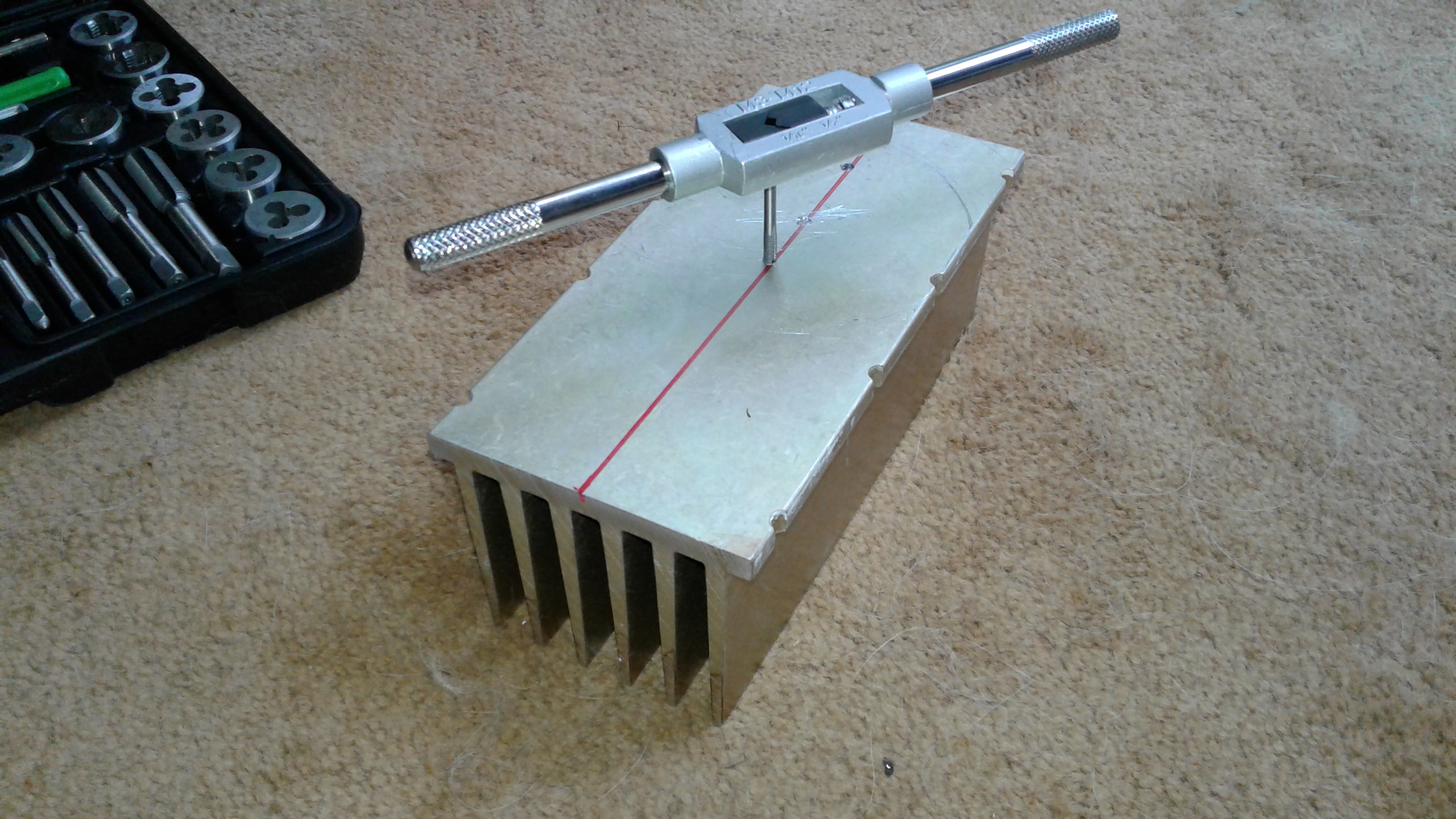
Tapping 6×32 threaded holes for mounting the SSR to the aluminum heatsink.
think it has happened to me before): ignore that 7/64″ drilling specification for a 6×32. Go with a 1/8″ bit. This lesson will stick, because I had to go to Harbor Freight and purchase a small set of replacement SAE taps after breaking the 6×32 off in the aluminum heatsink, a pack of replacement 1/8″ drill bits (I use that size a lot… and break them eventually), and a pack of replacement 7/64″ bits as well. I bought packs of seven of each size, which hopefully will get me through the weekend at least.
After marking two more hole locations (trust me, that broken off piece of 6×32 tap ain’t coming out of that aluminum — I just filed it on down flush with the aluminum), I then drilled new holes with a 1/8″ bit instead. Those tapped nicely with the shiny new 6×32 tap and the bolts fit snugly.
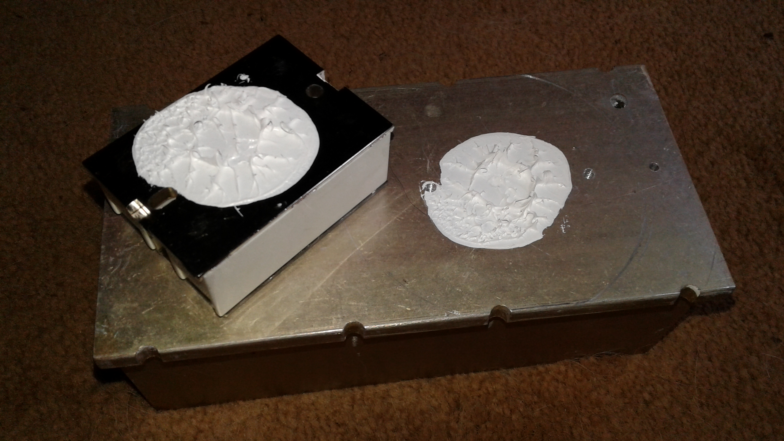
Is there really such a thing as using “too much” heat sink compound? Nah. “If it don’t ooze, it don’t cools,” is my motto.
To optimize thermal cooling of the SSR through the heatsink, I applied a copious amount of heat sink compound before attaching the SSR to the heatsink. The compound is cheaper than replacing an SSR, so I put enough on there that it oozed out from under the SSR when I tightened down the attachment bolts. How else is there to measure whether or not you applied enough heat sink compound, right?
Routing The AC Wiring From The SSR To Operate The Oven
Some guys get all fancy and rip the factory controls out their toaster ovens when doing this conversion, then spend tons of time cutting square openings for the LCD display of their controllers, drill new holes for pushbutton momentary contact switches, mount the SSR inside the oven case, put in a cooling fan for the SSR… etc. Being a bit more practical-minded, I opted for the “Let’s just build something that actually WORKS and dispense with spending hours and hours trying to make it look all fancy and compact and still only end up with something which looks like a mangled control panel and end up possibly melting down the Arduino, shield, and SSR because they’re right next to the cooking chamber” route. I don’t know whether “I took the road less traveled” on this part of the project, but I know for sure I took the one which works just as well (if not better) and took a helluva lot less time to end up with a useful reflow oven. To wit…
I simply cut the “hot” side of the oven’s AC power cord (carefully, avoiding nicking the
SSR mounted on heatsink and attached to the oven’s AC wiring and the reflow shield’s SSR drive terminals. After multiple back-to-back test runs, the SSR and heat sink assembly didn’t even get the least bit warm.
neutral side of the cable), stripped the two halves of the cut hot wire, crimped and soldered wire terminals on them, and firmly attached them to the AC terminals of the SSR.
The factory controls in the oven are simple: a couple of mechanical controls and a “power on” lamp. All that’s needed for reflow use is turn the temp knob to “toast” setting and the “off/on/timer” knob to the “always on” position. If there’s AC switched on to the power cord from the SSR, that sucker starts heating up. You don’t need (or want) to use the temperature control on the oven at anything other than the toast setting, because the reflow shield, Arduino, and the PID software code will handle switching the oven on, off, or effectively “pulsing” the power to control the rise and fall of the temperature inside the oven.
Test Reflow Run #1 — A Case Of “That Didn’t Go As Intended”
With all the Arduino IDE Sketch code and libraries installed in the Arduino and everything wired up it was time to test oven #2 under real conditions. Several test runs indicated it would ramp-up in temperature at a sufficient rate and would reach the maximum needed temperature. So, it was time to try reflow soldering a board — the real test.
Using a board marketed for “surface mount soldering practice,” I applied solder paste to several of the component locations and positioned the parts. I saw no reason to put every single part on the board, since it has no real function anyway. All I needed to know was whether or not the oven would actually reflow the soldering job successfully. Time to load the board in the oven and hit the “run” button and see what happens.
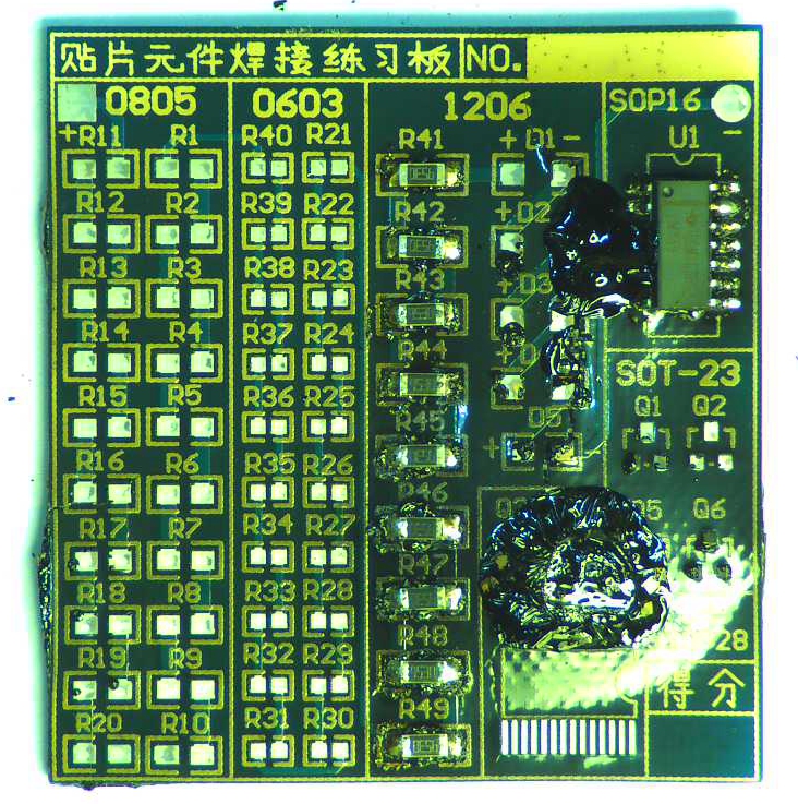
Not exactly the result we’re looking for. Reason numero uno for using a $1 soldering practice board and parts for initial testing of a reflow oven setup. I can’t read Chinese, but I suspect that lettering on the board might translate roughly to “Hey, y’all, hold my beer, watch this… and be prepared to run, just in case.”
Hmmm… there’s a reason it was called a “toaster” oven, because that’s exactly what it did to the first board. About three minutes into the process smoke started coming out of every possible point of airflow leakage in the oven — along with a godawful stench that I still haven’t gotten completely cleared out of the house after a couple of days. The board stinks so bad it’s relegated to the table out on the back patio. It’s horrendous. I don’t know the chemical composition of that circuit board or the components down to precisely enough detail to know for sure, but I wouldn’t be surprised if smoke detectors were going off in the next county — along with radiation detectors at the port down in Mobile, AL. I suspect there may have been some isotopes created during this meltdown that would have thoroughly impressed Robert Oppenheimer.
If At First You Don’t Succeed…
… run to Dollar General for three refills and fresh batteries for the automatic dispensing aerosol type air fresheners (all three of them), put on your stinking (I mean “thinking”) cap, make some tweaks and changes, and go at it again.
First thought: the fact that I had laid the circuit board directly on the metal rack just above the lower heating element probably exposed parts of the board to almost direct heat from the element, and the metal rack itself probably caused differences in heat dispersion along and inside the circuit board. I’d seen guys on YouTube just throw their circuit boards right on the rack and they claimed to get good results. Perhaps this particular board had a really cheap solder mask on it? Or maybe those guys were using ovens with wattage roughly equivalent to those old incandescent lightbulb powered Easy-Bake Ovens sold for children?
Idea: place a sheet of aluminum foil on the rack over that lower element to further diffuse the heat. Another idea: use some means of keeping the board from having direct contact with the rack or the aluminum foil sheet. I decided to implement both ideas for good measure.
I also went into the Arduino Sketch code and adjusted the pre-soak and reflow maximum temperatures downward a bit. I set them to levels still above the minimum recommended temps for the reflow profile of the solder paste I like to use, but below the maximums.
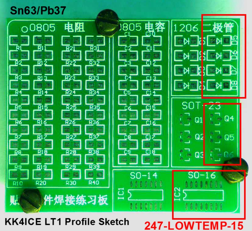
Test board #2. The areas in the red rectangles indicate where I applied lead-free, low temp solder. All other pads used for testing were to have an Sn/Pb solder paste applied.
I grabbed another solder practice board and drilled three 7/64″ holes in the board in areas where there were no solder pads or components to be placed. Just the right size for some M4 bolts to be inserted along with nuts. These served as adjustable height standoffs to keep the board up off the aluminum foil.
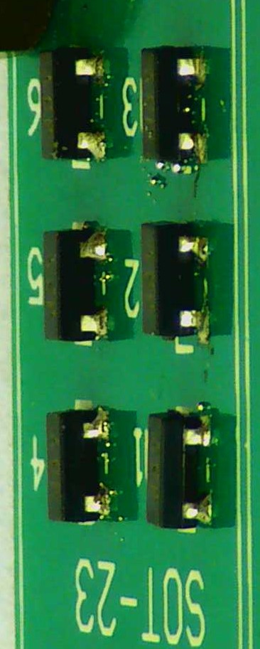
Once again, I chose not to place every possible part on the board. Rather, I placed the two IC’s, all of the diodes, all of the SOT-23 devices, and numerous resistors, making sure I had components at all corners of the board, edges, and the center area, because I wanted to make sure that the solder reflowed properly on all areas of the board and that no areas appeared were damaged by excessive heat.
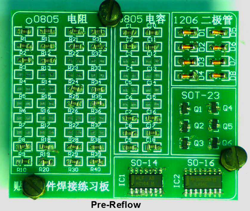
Test board #2, with solder pastes applied and components in place, ready to go into the reflow oven.
As noted in the photo, I used two different solder pastes which I had on hand so that I could determine whether one paste appeared to work significantly better than the other. One of the two pastes was a lead-free, low temp formulation, and the other was a leaded paste (hey, I’m not shooting for ROHS compliance at this stage — I just want to be able to reflow solder a whole board of components in an easier, faster manner.)
I loaded the board in the oven and hit the “run” button to fire up the reflow oven — this time running my modified code in the Arduino/Reflow Shield controller.
Success! Not only did the temps get controlled nicely, but because the temperature setpoints were a bit lower, the process ran within the recommended time window as specified in the solder paste reflow profile.
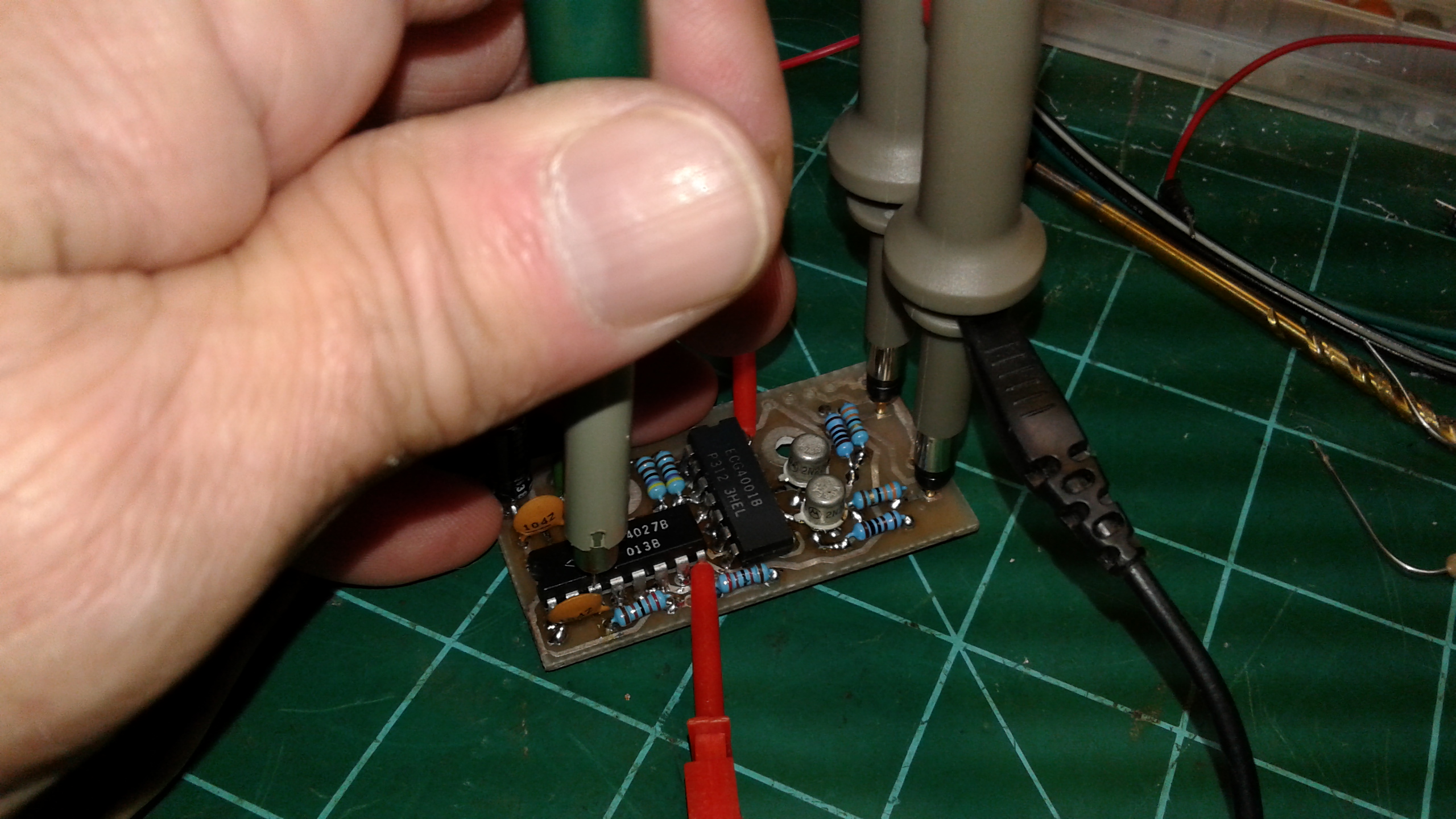
Success At Last!
I am quite pleased to report that things turned out great on the second test board reflow run. To wit, I’ll just leave you with these photos showing the reflow soldering results
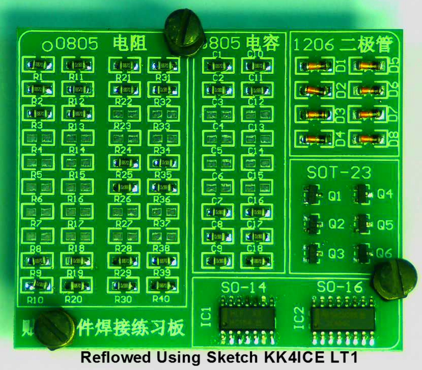
Test board #2 after reflow oven run.
achieved. While you’re looking at these, I’ll be busy searching some more for that blank JumboSpot/ZumSpot clone board which my buddy gave me a few weeks ago. He brought over a huge Digi-Key box yesterday with all the components required to actually assemble a couple of DMR “hotspot” boards. Now, if I can only find where I misplaced the stupid board…
73,
KK4ICE
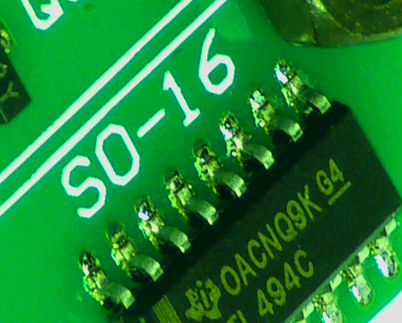
SO-16 IC after reflow run.
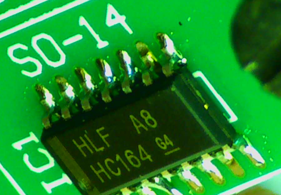
SO-14 IC after reflow run.
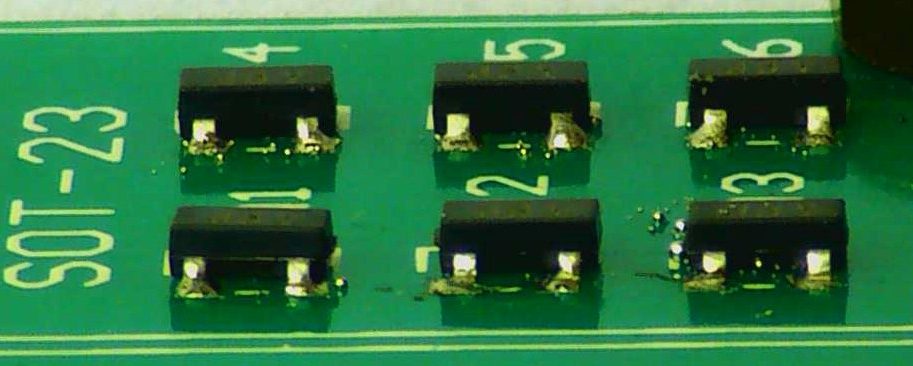
SOT-23 devices after reflow run.
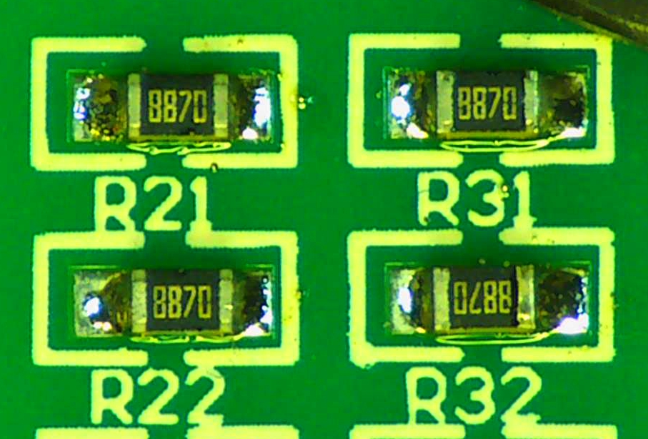
Resistors after reflow test #2.
Recent Comments