Doing the engineering work on a multi-site, simulcast paging system necessitates keeping a check on the operational status of several transmitters which are — by design — geographically spread out all over the place. Anything which can automate some of the process of testing (and, ideally, provide remote, real-time monitoring) is a huge help. Not only does it save troubleshooting time (many problems can be pinpointed from here in the lab before even going to a site to troubleshoot), but it also minimizes potential downtime by automatically alerting us if certain problems ever do occur. It’s all about providing the most reliable service possible, while making any need repairs or system adjustments in the shortest amount of time possible.
The goal of this project was to put together a system for over-the-air monitoring of signals on a simulcast system which drives paging transmitters at multiple sites. I had
originally started putting it together using a Quintron/G.E. Link Receiver Radio; however, I really wanted to keep that radio reserved as a spare. At the same time I wanted to build a fully functional, permanently installed monitoring/telemetry system which not only
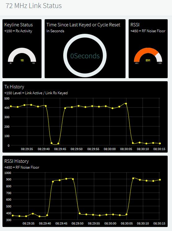
Figure 2: Online view of telemetry and status indicators during simulcast signal activity. Includes up to an hour of continuous timeline graphing of the “Key” voltage/status and the RSSI level, which starts graphing whenever I load or refresh the telemetry page. After an hour, it continues go graph both timelines, with the oldest activity simply rolling off to the left. If needed, I can quickly modify the one hour timeline to whatever time span suits my needs.
provides me with internet-based, real-time monitoring of the operation of the link transmitter system (the backbone of the whole paging operation) AND would automatically send a text alert to my cell phone should there be no simulcast/link signal activity for a certain amount of time (the paging system is set to send an automatic “test” messages to selected pagers at given intervals.) Not wanting to tie up the Quintron/G.E. radio, I opted for plan-B and grabbed a Glenayre link receiver radio to use instead.
The Glenayre RL-72 turned out to be a better choice anyway. It has the added benefit of an analog RSSI (Received Signal Strength Indicator) output on its back panel connector. That gave me the ability to add the RSSI to the information displayed on the IoT/telemetry dashboard.
I put both timeline graphs on the telemetry dashboard so that I can just leave the dashboard loaded and running on a computer if I want to just occasionally stop by and glance at the simulcast activity. With the timelines both set the same, it’s very easy to eyeball the two timelines, and whenever there is a peak on the RSSI graph, there should be a corresponding “dip” on the key/activity graph, indicating good signal quality from the simulcast transmitter caused the transmitter “key” (an open-collector type circuit) to pull “low,” which would normally be used to in key up an attached digital exciter and P.A. if it were running at one of the sites. As a possible troubleshooting example: seeing a peak on the RSSI

Figure 3: View of the telemetry dashboard during an idle period (no signal being received from the simulcast transmitter.)
graph without a corresponding dip on the keyline graph would tell me that either there was some sort of co-channel interference signal received, or there might be some sort of distortion in the signal from the simulcast transmitter which would call for immediate investigation.
The complete build of this telemetry system took quite a few hours in all, but it was worth the effort. The RL-72 radio is actually only 1/2 the width of a standard rack mount in size, so the manufacturer equipped it with an extension flange which has pre-drilled holes located such that a delay unit can be added (a necessity in simulcast paging operations using a common frequency at all the transmitter sites — otherwise the digital signals could become garbled if received out of phase in critical coverage areas.)
I took advantage of that extension/accessory flange as a convenient location for mounting the Arduino and the Ethernet shield (see figure 4.) I also popped out one of the little plastic plugs which Glenayre had in the pre-drilled
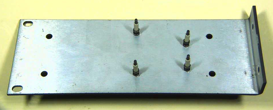
Figure 4: holes drilled, with bolts and stand-offs placed for mounting the Arduino and Ethernet shield.
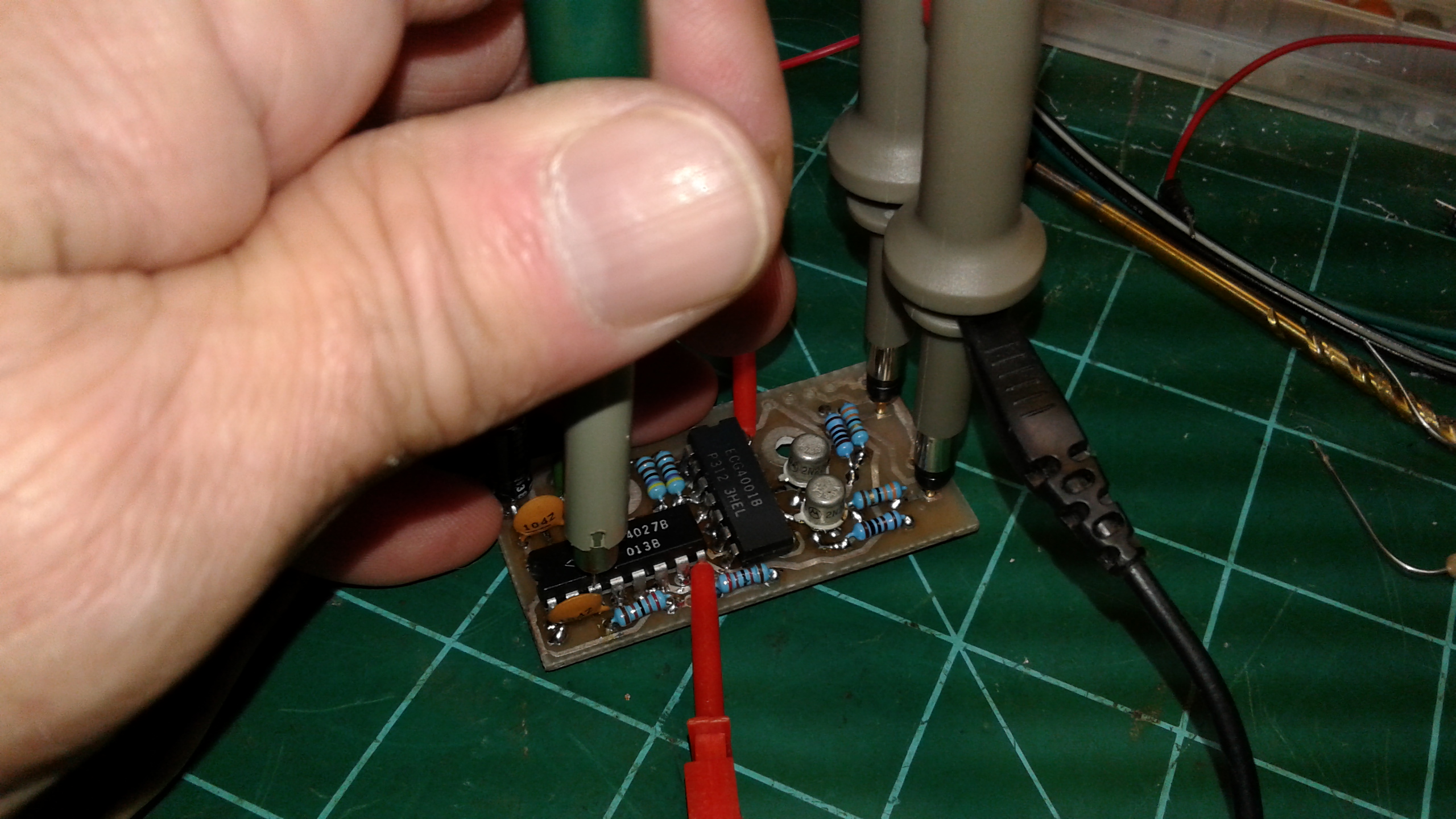
holes for the delay unit and replaced it with a pop-in LED mount. That LED is attached between the keying line and ground, with a dual-purpose resistor in series. The obvious purpose of the resistor is to serve as a current limiter. The key line is sitting at around 12 volts when floating open, which would blow the LED. The second purpose of the resistor is to form a voltage divider in conjunction with the LED’s normal voltage drop, which needs to be 5 volts or less (the maximum safe input voltage for an analog input pin on the Arduino.)
The Arduino and Ethernet shield had already been temporarily assembled and connected to the receiver for the purposes of writing and tweaking the IDE Sketch code
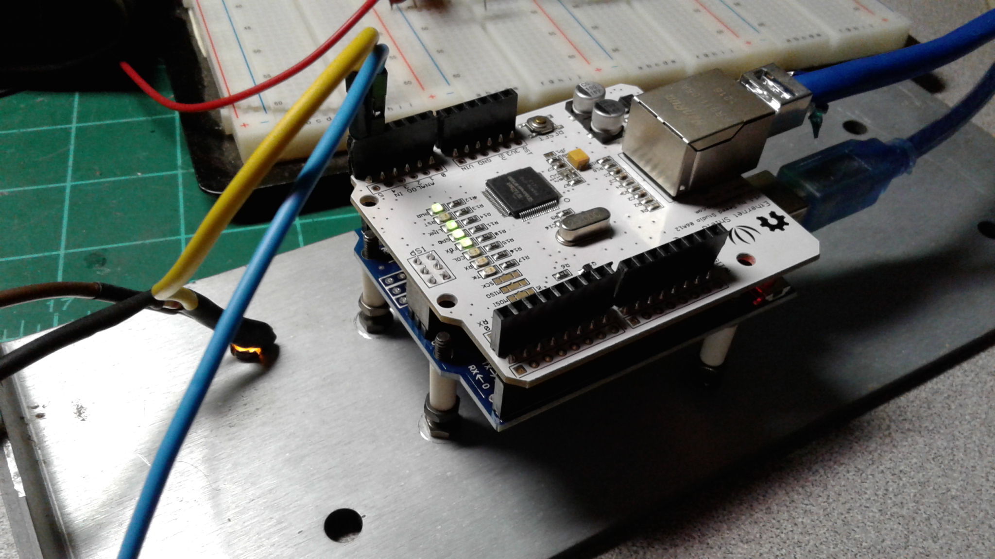
Figure 5: Arduino Uno R3 with Ethernet shield, attached to mounting bolts. The LED can be seen to the left of the Arduino assembly.
which monitors all the signals, provides the necessary logic functions, formats the data, and pipes it all to an IoT website which hosts the dashboard. The chosen mounting location turned out be perfect for the job, with plenty of space for attaching the power supply cable, Ethernet cable, and all of the signal lines without things getting all jammed up (see figure 5.)
With the Arduino assembly secured to the extension/accessroy flange, it was simply a matter of reattaching the flange to the side of the side of the RL-72 radio and it was ready to be permanently installed in a rack cabinet here in the lab (see figure 6.) I

Figure 6: Assembled system, ready to be installed in the test equipment rack.
alrerady had a Quintron (i.e. “Glenayre”) DC power supply installed in a test equipment rack near the workbench for convenience when servicing or repairing any of the equipment which runs on 24-30 VDC. A couple of rackmount clips and screws and the newly build telemetry/monitoring system was in its new home here in the lab and fully operational (as shown in figure 7 and in the above video.)
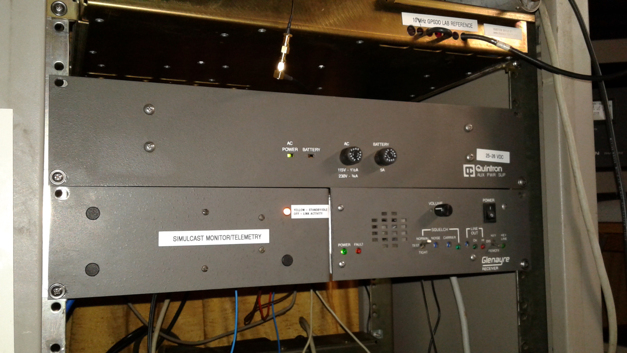
Figure 7: Glenayre RL-72 Link Radio with added Arduino-based internet accessible telemetry, mounted underneath its accompanying DC power supply here in the lab.
Mission accomplished. At the time of this post, the only work remaining is to clean up all the mess, gather up all the tools, and sit back and let this little creation do its thing. Oh, and find a really obnoxious sounding ringtone/alert tone that will wake me up in the event this thing ever does end up detecting a problem at night, etc. Those factory sound files on cell phones don’t even phase me while I’m sleeping.
One of life’s nagging, still unanswered questions: Why is it that that the cell phone manufacturers equip their phones with some of the most annoying autocorrect and predictive text functions, but they can’t include alert tones that wouldn’t get your attention if you had earbuds hooked up and stuck in your ears?
Recent Comments